Two-way pneumatic control valve

A technology of pneumatically controlling valves and valve stems, which is applied in the direction of lifting valves, valve details, valve devices, etc., which can solve the problems of easy backflow of liquids, lax functions, and loss of control, etc., so as to improve reliability, prevent springs from sticking, and improve The effect of job reliability

Active Publication Date: 2018-09-11
SHANXI PINGYANG IND MACHINERY
View PDF10 Cites 3 Cited by
  • Summary
  • Abstract
  • Description
  • Claims
  • Application Information

AI Technical Summary

Problems solved by technology

[0007] The present invention provides a two-way pneumatic control valve to solve the technical problems of current pneumatic control valves, which are prone to backflow of liquid and loose function out of control.
[0009] For the first

Method used


Image

  • Two-way pneumatic control valve
  • Two-way pneumatic control valve
  • Two-way pneumatic control valve

Examples


Embodiment Construction

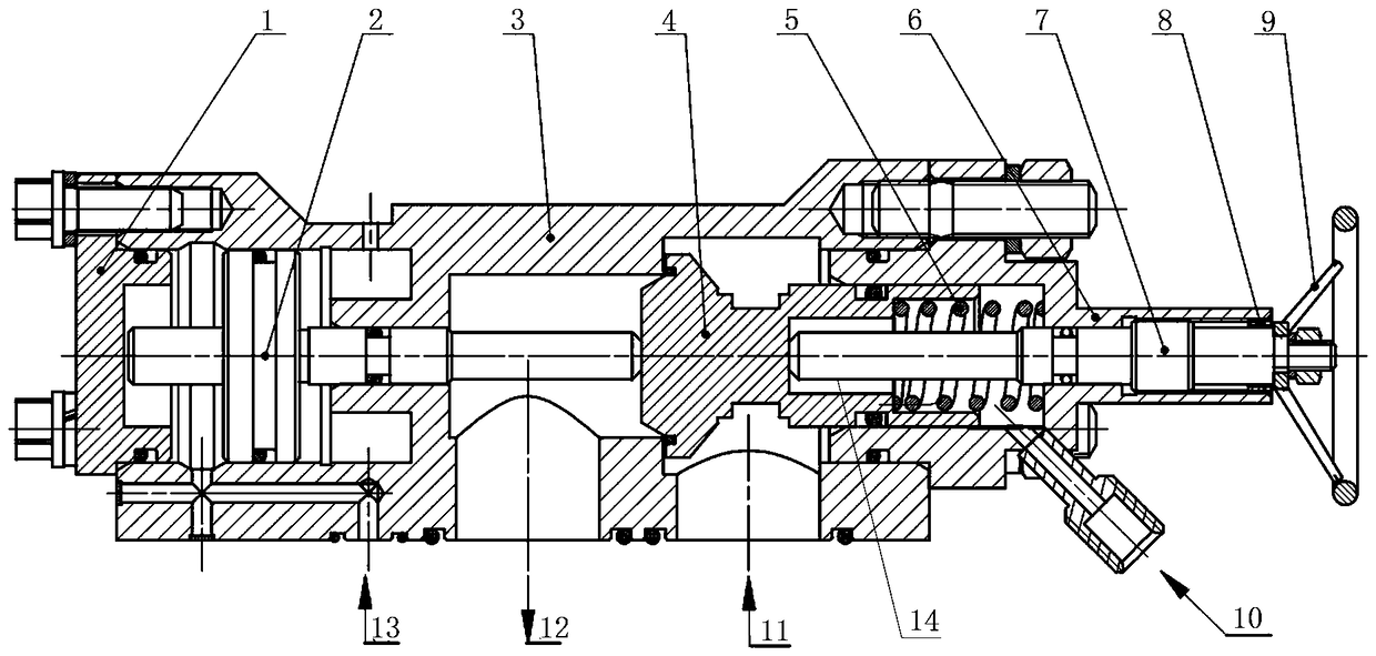
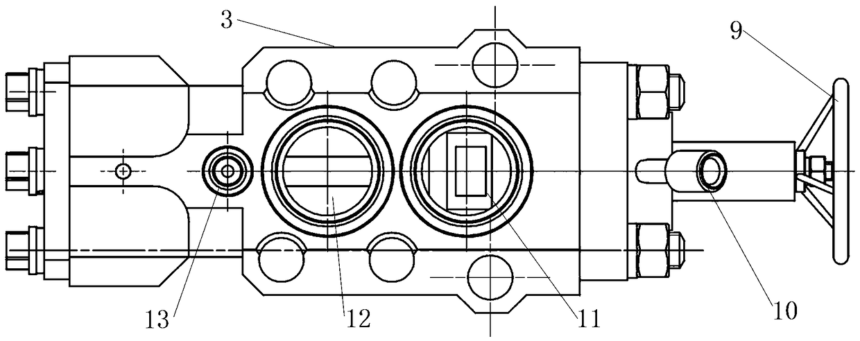
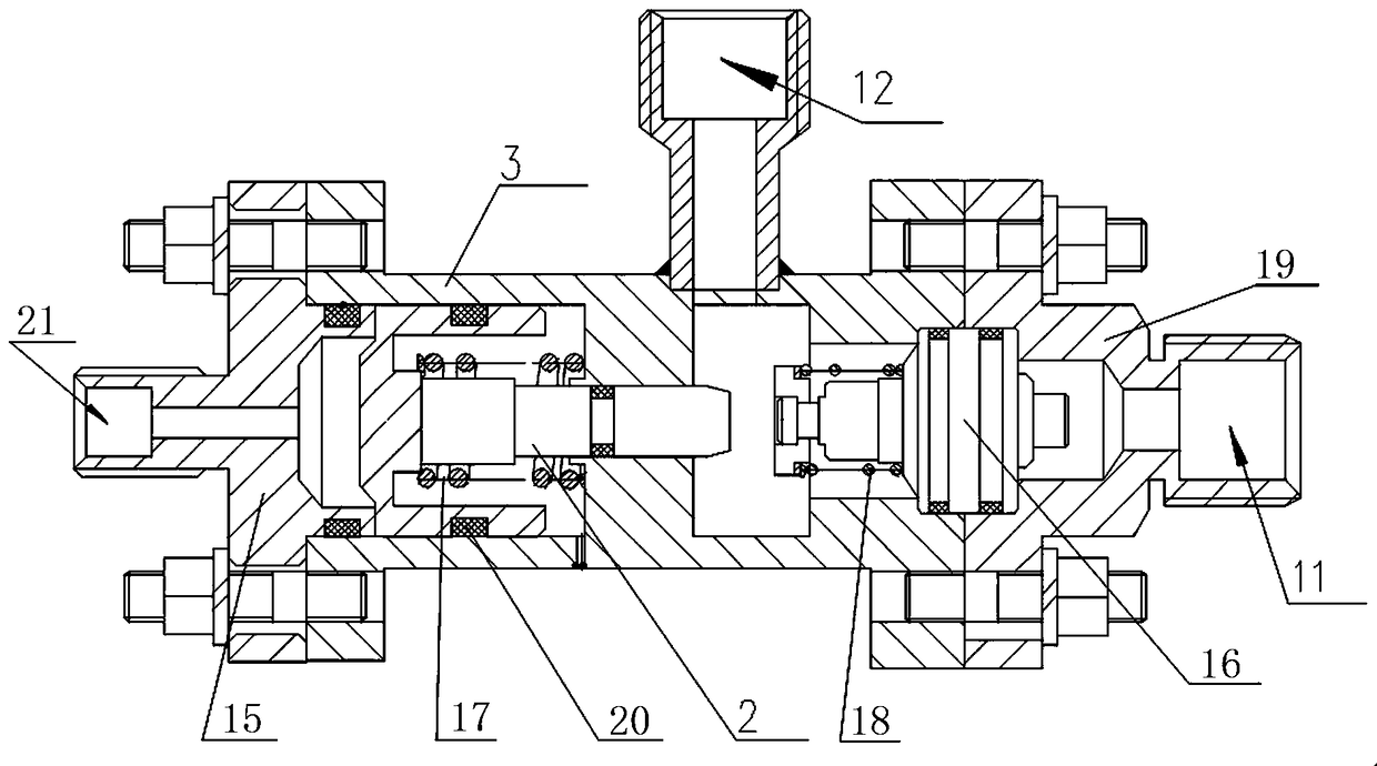
[0022] A two-way pneumatic control valve, comprising a housing 3 with a liquid inlet 11 and a liquid outlet 12, a plunger 2 arranged in the housing 3, and a valve core 4 matched with the plunger 2 for opening and closing the liquid inlet 11; The front end of the spool 4 is used to open and close the liquid inlet 11. A cavity is formed between the end of the spool 4 and the housing 3. The housing 3 has a first control air inlet 10 connected to the valve. The cavity formed by the end of the core 4 and the housing 3; the end of the valve core 4 is provided with a valve rod 14, the front end of the valve rod 14 is opposite to the end of the valve core 4, and the end of the valve rod 14 slides on the housing 3, The valve stem 14 is sheathed with a return spring 5 which is in contact with the end of the valve core 4 ; the housing 3 is also provided with a second control air inlet 13 for inputting external air to control the movement of the plunger 2 .

[0023] A locking pin 7 whose ...


PUM


Abstract

The invention relates to the field of mechanical pneumatic control, in particular to a two-way pneumatic control valve. The technical problems that as for an existing pneumatic control valve, liquid is prone to flowing back, the pneumatic control valve cannot be closed tightly, and consequently, the function gets out of control are solved. The two-way pneumatic control valve comprises a shell provided with a liquid inlet and a liquid outlet, a jacking rod arranged in the shell, and a valve element matched with the jacking rod and used for opening and closing the liquid inlet; the front end ofthe valve element is used for opening and closing the liquid inlet, a cavity is formed between the tail end of the valve element and the shell, and the shell is provided with a first control gas inletwhich communicates with the cavity formed by the tail end of the valve element and the shell; the tail end of the valve element is connected with a valve rod, the tail end of the valve rod is slidably limited to the shell, and the valve rod is sleeved with a return spring; and the shell is further provided with a second control gas inlet used for inputting external gas for controlling action of the jacking rod. The structure of a valve communicating the inlet with the outlet is improved, a path is opened or closed by adopting a control gas driving mode, and the problem of possible backflow issolved.

Description

technical field [0001] The invention relates to the field of mechanical pneumatic control, in particular to a two-way pneumatic control valve. Background technique [0002] Usually used in the field of pneumatic control image 3 The pneumatic control valve is used to realize the control of other substances such as liquid or gas. Its working principle is: through the control air inlet, the control air pressure is applied to the ejector rod, and the spring is compressed to push the one-way valve to open, so that the controlled liquid Through the liquid inlet to the liquid outlet. When the pressure of the control gas at the control gas inlet is removed, the spring returns to close the one-way valve, and the push rod resets, so that the passage between the liquid inlet and the liquid outlet is closed. [0003] But this type of pneumatic control valve has the following problems: [0004] ① When the whole set of test equipment is not in use, when the pressure of the liquid outle...

Claims


Application Information

Patent Timeline
IPC IPC(8): F16K1/32F16K31/12F16K27/02F16K35/00
CPCF16K1/32F16K27/02F16K31/12F16K35/00
Inventor 李建波王占军张毅陈志伟杨磊张云飞
Owner SHANXI PINGYANG IND MACHINERY
Why Eureka
Try Eureka