Electrifying control circuit

A technology of electric control and circuit, which is applied in the field of power-on control of state detection circuit, can solve the problems of waste of detection device resources and low validity of detection results, etc.

Active Publication Date: 2009-12-30
SHANDONG LUNENG AOTE TECH
View PDF0 Cites 4 Cited by
  • Summary
  • Abstract
  • Description
  • Claims
  • Application Information

AI Technical Summary

Problems solved by technology

[0003] Continuously detect a device that has been in a stable state for a long time, the validit...

Method used


Image

  • Electrifying control circuit
  • Electrifying control circuit

Examples


Embodiment Construction

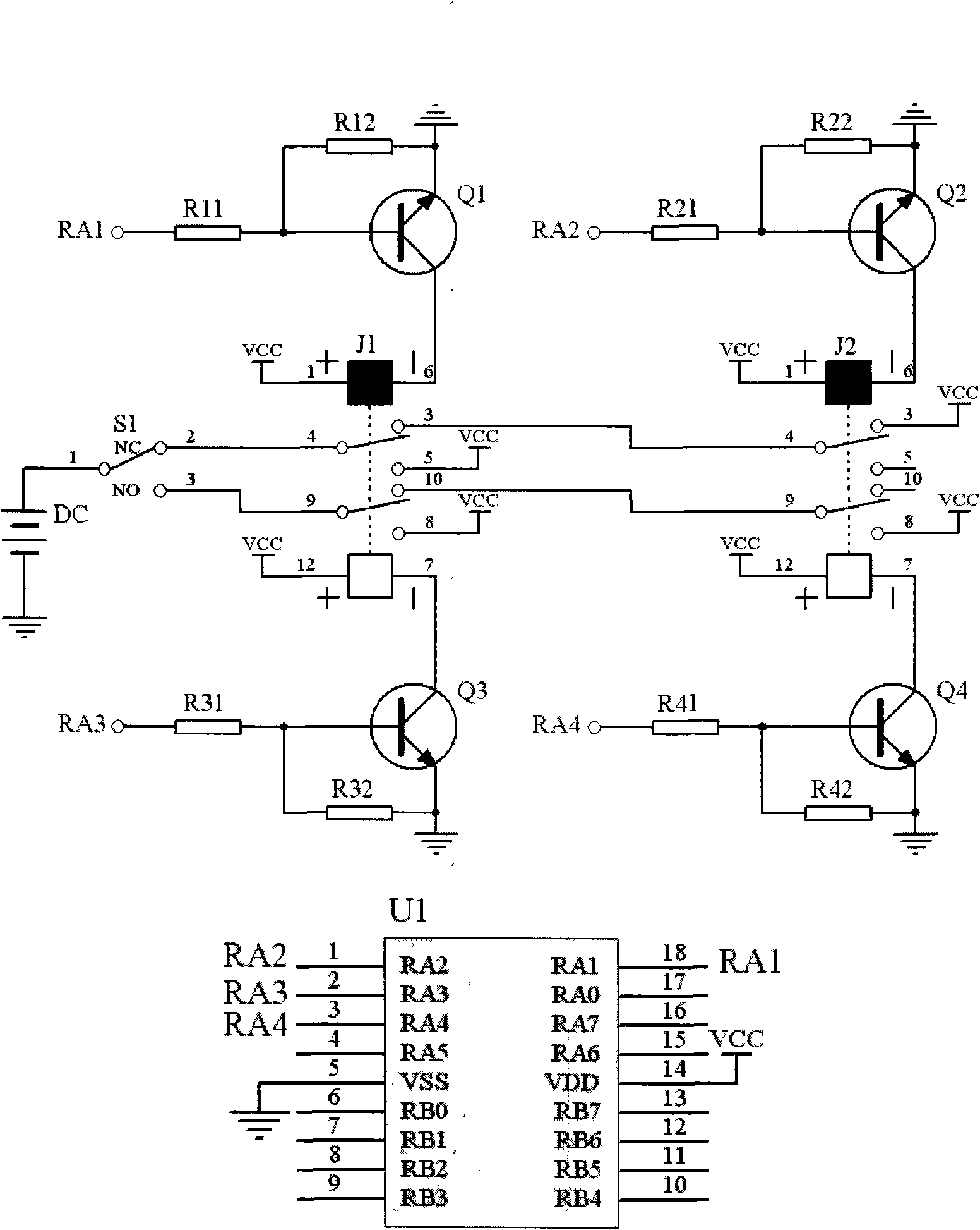
[0010] Below in conjunction with accompanying drawing and embodiment the present invention will be further described:

[0011] like figure 1 As shown, the single-chip microcomputer U1 has at least four I / O ports for running embedded software. Its function is to control the level of the I / O ports at the beginning of power-on or power-off to realize the control of the forward and reverse coils of the relay. Control, and then make the relay act, complete power-on or power-off, and other I / O ports can realize other functions such as device status detection. The single pole double throw switch S1 is used to trigger the control circuit by the detected device, and the detected device can make the normally open or normally closed node of the single pole double throw switch S1 be connected through mechanical means. Relays J1 and J2 with dual channels of forward and reverse coils can realize the on-off control of the circuit under the control of the single-chip microcomputer U1 and the...


PUM


Abstract

The invention discloses an electrifying control circuit which comprises a singlechip U1 provided with at least four I/O interfaces, two stick relays J1 and J2 with forward and reverse coils and double channels, four groups of relay coil drive circuits and a single-pole double-throw switch S1. The control circuit triggers the circuits to electrify when the state of equipment is switched, and automatically powers down after the state collection is determined to be right; when the state of the equipment shakes, the circuit can still normally work, when the equipment is in a stable state, the circuit is also in a power down state, therefore, the circuit has the function of preventing shaking, can ensure that each detection of a detection device is effective and the collected state information of the equipment is immediate and accurate, also reduce the energy consumption and save the energy resource.

Description

technical field [0001] The invention relates to a power-on control circuit, which is mainly applied to the power-on control of a state detection circuit of a device with two states. Background technique [0002] For some devices with two states, such as windows, doors, etc., the state change is completed instantaneously, and most of the time the device is in a stable state of "open" or "closed". If you want to detect the state of such equipment, the general method is to use a continuously working detection device to continuously detect. In this way, the detection results are only useful when the equipment is in motion. At other times, the equipment is in a steady state and the detection results remain Unchanged, is useless. [0003] Continuously detecting a device that has been in a stable state for a long time will not be effective in the detection results, and will also waste a lot of detection device resources. Contents of the invention [0004] Aiming at the shortcom...

Claims


Application Information

Patent Timeline
IPC IPC(8): G05B19/042
Inventor 魏光村朱建伟郭卫东林志贤
Owner SHANDONG LUNENG AOTE TECH
Why Eureka
Try Eureka