Automatic card sending machine

A technology of automatic card issuance and driving mechanism, which is applied to machines for issuing pre-printed tickets, computer components, auxiliary ticket issuing devices, etc., which can solve the problems of wasteful use of card capacity space, high machine cost, troublesome operation, etc., and reduce downtime The frequency of replacing the card storage mechanism, the low cost of the machine, and the effect of saving labor

Inactive Publication Date: 2009-12-30
曾蕴仪
View PDF0 Cites 21 Cited by
  • Summary
  • Abstract
  • Description
  • Claims
  • Application Information

AI Technical Summary

Problems solved by technology

However, compared with manual card issuing, the height of the card outlet of the automatic card issuing machine is constant, and it cannot be adjusted according to the height of the driver's cab. It is convenient to take out the card. The existing automatic card issuing machine is usually equipped with two card issuing ports, the upper and the lower. The card issuing equipment independently issues cards through separate card issuing equipment, and its automatic card issuing machine has two sets of card issuing equipment, which not only has high machine cost, complicated structure, and difficult maintenance
And in order to facilitate installation and maintenance, a certain space needs to be reserved between the upper and lower sets of card issuing equipment for operation during installation and maintenance, which occupies the relatively narrow space of the original card storage mechanism, so that the amount of card storage is not much In particular, the user should use the most advanced path induction card (with the ability to sense and record the information of each intersection passed by the vehicle, accurately measure the actual driving path of the vehicle, and make the account removal and charging of the owners of the expressways charged by the network easier. For accurate and reasonable functions), because the path induction card has a battery, the thickness of the card is 5-6mm / sheet, which is 7-8 times thicker than the currently used IC card, and its storage capacity is even smaller. Adding cards is cumbersome to operate, and it doesn't make much sense to save labor
In addition, the number of high and low vehicles through the automatic card issuing machine cannot be the same, and the upper and lower card storage mechanisms cannot make full use of the card storage space at the same time. The use of card capacity space is wasted, which will increase the work of adding cards, especially for high-end vehicles. 1. When the number of low-end models is very different, there is often a serious backlog of cards in one card storage mechanism, while another card storage mechanism needs to add cards frequently, and the workload of adding cards is even greater.

Method used


Image

  • Automatic card sending machine
  • Automatic card sending machine
  • Automatic card sending machine

Examples


Embodiment 1

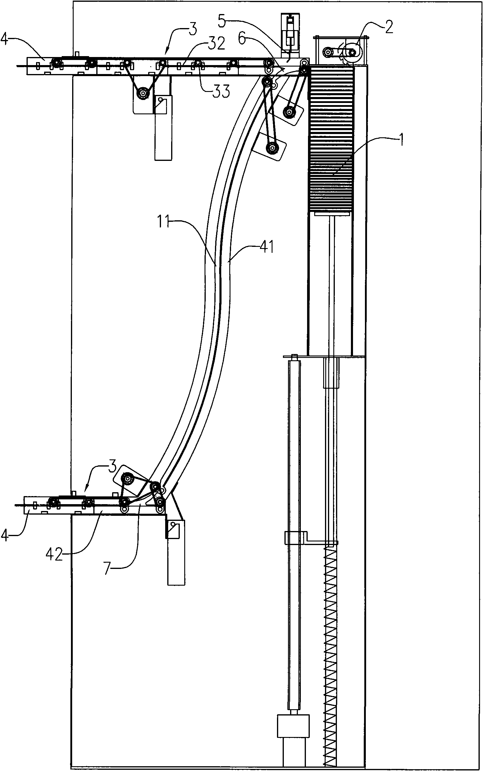
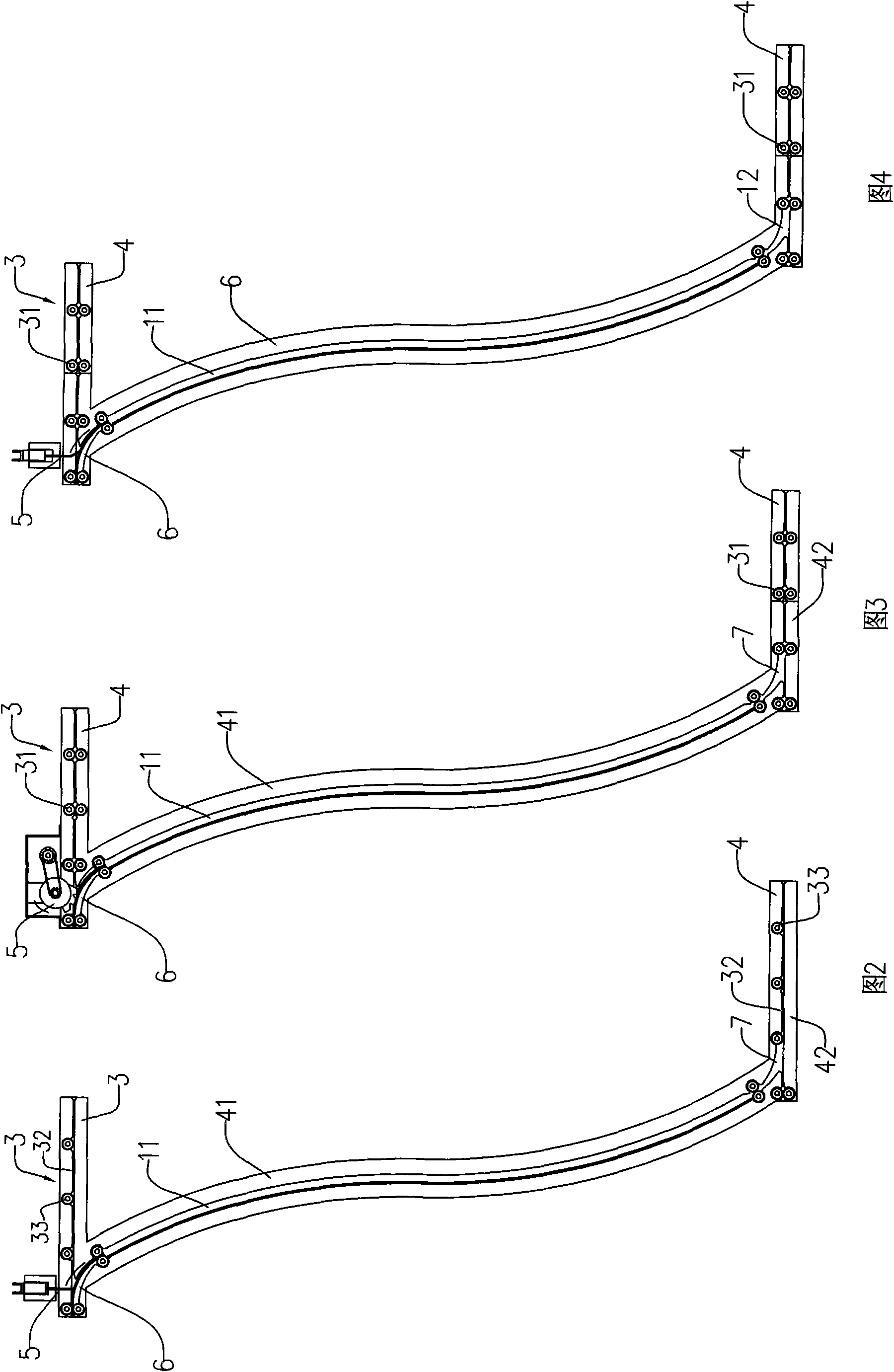
[0012] An automatic card issuing machine, such as figure 1 , including a card storage mechanism 1, a card dial mechanism 2 for pulling out cards in the card storage mechanism 1 one by one, a card delivery channel and a card delivery mechanism for sending out cards in the card delivery channel, and the card delivery channel is divided into upper and lower The lower two card-discharging channels 4 with different heights, the upper card-discharging channel and the lower card-discharging channel are all equipped with a card feeding mechanism 3 that sends out cards in the channel along the channel. The dialing mechanism 2 can be a friction wheel driven by a motor or a dial with convex teeth driven by a motor (such as figure 1 ) and other existing automatic card issuing machines. Described card feeding mechanism 3 can adopt the card feeding mechanism commonly used in the existing card issuing machine, for example: many pairs of rollers 31 that can be clamped and distributed at inte...

Embodiment 2

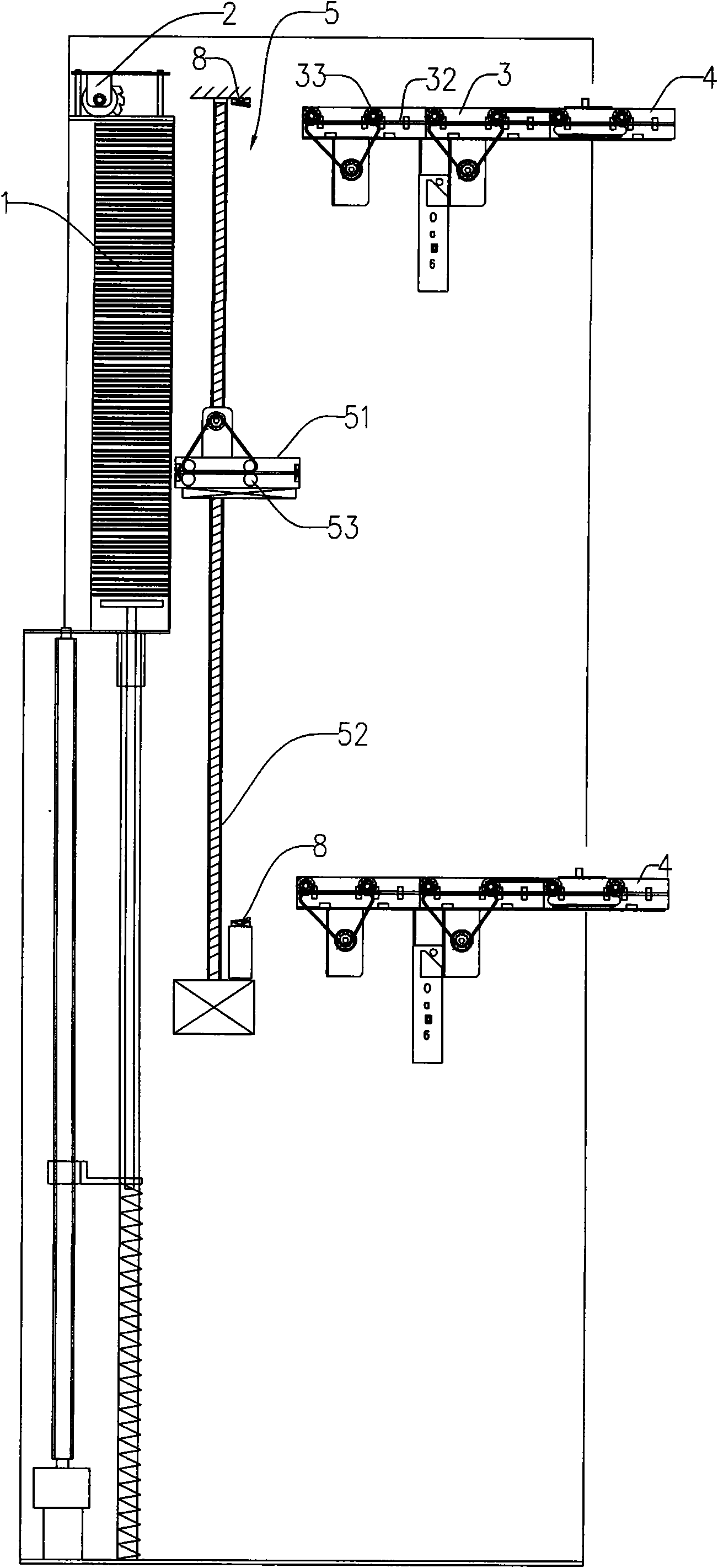
[0022] An automatic card issuing machine, such as Figure 5 , including a card storage mechanism 1, a card dial mechanism 2 for pulling out cards in the card storage mechanism one by one, a card guide mechanism 5, two upper and lower parallel card outlet channels 4 with different heights. The card guide mechanism includes a card transport mechanism 51, a drive mechanism 52 for driving the card transport mechanism to move up and down, and a card delivery mechanism 53 installed on the card transport mechanism for transporting cards. The driving mechanism 52 is a screw mandrel driven by a motor, and the card transport mechanism 51 is mounted on the screw mandrel by a nut matched with the screw mandrel. When the motor drives the screw mandrel to rotate, the card transport mechanism moves up and down along the screw mandrel. The rear end of the card transport mechanism 51 is flush with the front end of each card output channel 4 . The card feeding mechanism 53 can be a pair of rol...


PUM


Abstract

The invention discloses an automatic card sending machine comprising a card storage mechanism, a card poking mechanism for poking cards in the storage mechanism into a card forwarding channel one by one and a card forwarding mechanism for forwarding the cards in the card feeding channel; wherein, the card forwarding channel comprises two or more than two card feeding channels having different longitudinal heights, and a card guiding mechanism can control the cards to enter different card feeding channels. Although the automatic card sending machine is provided with only one card forwarding mechanism, one fewer than the existing automatic card sending machine has, the automatic card sending machine is still capable of forwarding cards to two or more than two card feeding channels having different heights, therefore, compared with the existing automatic card sending machine, the invention not only meets the requirements for vehicles of various cab heights, but also greatly expands the card storage space of the card storage area and further expands the card storage capacity. The invention can not only satisfy various requirements of users, but also send cards to both high-cab and low-cab vehicles in a balanced manner by making full use of the capacity of the card storage mechanism; and additionally, the invention has the advantages of lower cost and lower failure rate by arranging only one card forwarding mechanism.

Description

Technical field: [0001] The invention relates to an automatic card issuing machine used in a highway toll collection system. Background technique: [0002] At present, unattended automatic card issuing machines have been used in the entrance issuing lanes of expressway toll stations to replace manual card issuing, which not only saves labor costs, but also eliminates the loss of cards and cheating in entry information writing that exist in manual card issuing. loophole. However, compared with manual card issuing, the height of the card outlet of the automatic card issuing machine is constant, and it cannot be adjusted according to the height of the driver's cab. It is convenient to take out the card. The existing automatic card issuing machine is usually equipped with two card issuing ports, the upper and the lower. The card-issuing equipment issued independently through their own card-issuing equipment, and its automatic card-issuing machine has two sets of card-issuing e...

Claims


Application Information

Patent Timeline
Patent Type & Authority Applications(China)
IPC IPC(8): G06K17/00G06K13/00G07B3/00G07B5/00
CPCG07B3/04G06K13/103
Inventor 曾蕴仪温丽斯
Owner 曾蕴仪
Why Eureka
Try Eureka