Method for coding two-dimensional optical identification code, identification system and printed product thereof

A coding method and identification system technology, applied to printed matter, printing, record carriers used by machines, etc., can solve problems such as reading errors, easy loss, and increased printing difficulty

Inactive Publication Date: 2009-12-30
GENERALPLUS TECH INC
View PDF2 Cites 59 Cited by
  • Summary
  • Abstract
  • Description
  • Claims
  • Application Information

AI Technical Summary

Problems solved by technology

[0006] Although the dots in this scheme are relatively evenly distributed than the aforementioned coding diagram, since each information point of the coding diagram is surrounded by 4 grid points, under the same density of dots in the printed coding diagram, it can Expresses less encoded information
However, when the density of information points 3 is higher, the visual effect will be worse, and the human eye is more likely to perceive the existence of the coding map, which increases the chance of confusing the coding map with the main information represented.
[0007] In addition, when the coding map is formed on a limited object surface area, under the premise of providing the same amount of information, the too high distribution density of information points will cause the distance between two adjacent information points to be too small; if we want to reduce this - visual interference, usually need to further reduce the size of the information point, but too small size will increase the resolution requirements of the printing machine and paper, and it is easy to miss during printing, which increases the difficulty of printing, and is easy to cause reading errors or Difficult to distinguish
On the other hand, if the distance between information points is simply increased to avoid too dense points in the coding pattern, the amount of information carried by the two-dimensional optical identification code will decrease.

Method used


Image

  • Method for coding two-dimensional optical identification code, identification system and printed product thereof
  • Method for coding two-dimensional optical identification code, identification system and printed product thereof
  • Method for coding two-dimensional optical identification code, identification system and printed product thereof

Examples


Embodiment Construction

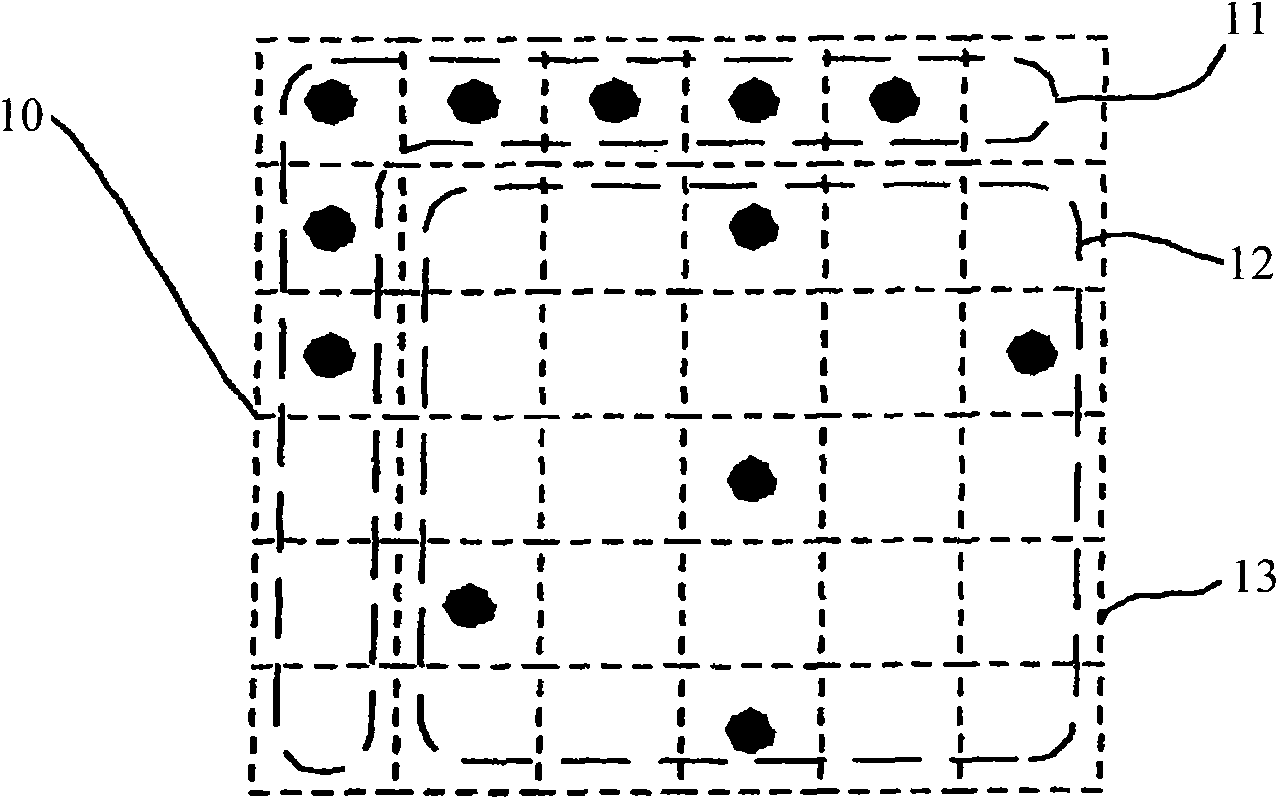
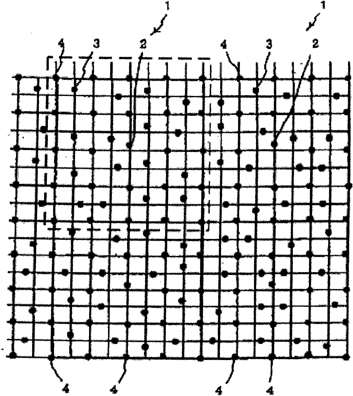
[0029] image 3 It shows a coding pattern formed by arranging a plurality of two-dimensional optical identification codes 10 designed in an embodiment of the present invention, Figure 4 show image 3 The coding diagram of the single two-dimensional optical identification code 10 in the figure clearly illustrates the design of the present invention. Please refer to Figure 4, the two-dimensional optical identification code includes a positioning block 101 and eight data coding blocks 102-109, and the nine blocks constitute an encoding pattern of a two-dimensional optical identification code. The eight data encoding blocks 102-109 and the positioning block 101 are arranged into a nine-square grid, that is, nine rectangles shown by dotted lines in the figure. The positioning block 101 is designed mainly to allow the optical reading device that reads the two-dimensional optical identification code to identify the reading direction. Therefore, in the positioning block 101 , fo...


PUM


Abstract

The invention discloses a method for coding a two-dimensional optical identification code, an identification system and a printed product thereof. The two-dimensional optical identification code is provided with a positioning block and a plurality of data coding blocks at four sides of the positioning block; both the positioning block and the data coding blocks contain a plurality of designated patterns arrayed in N*M arrays; and the asymmetrical designated patterns consisting of a random row and a random column in the positioning block are filled, at least one designated pattern of the data coding blocks in the center is filled, and the residual designated patterns in the data coding blocks are selectively filled to express a binary code respectively, wherein N and M are natural numbers.The identification system comprises an optical reading device, a processing device and an output device, and is used for identifying coding information contained in the two-dimensional optical identification code on the printed product.

Description

technical field [0001] The present invention relates to a technology of an optical identification code, and in particular relates to a coding method of a two-dimensional optical identification code, an identification system and a printed matter containing the two-dimensional optical identification code. Background technique [0002] Optical Identification Code (Optical Identification, OID) is a technology that can hide digital data in ordinary printed matter and retrieve hidden digital data. It can hide digital data in ordinary printed matter through standard printing procedures and standard inks , coexisting with the original pattern on the print. Through the optical and image processing technology of the optical identification pen (OID Pen), the data hidden in the printed matter can be retrieved in advance. [0003] In the prior art, each optical identification code coding pattern is generally composed of many fine information points, and these information points are dist...

Claims


Application Information

Patent Timeline
Patent Type & Authority Applications(China)
IPC IPC(8): G06K19/06G06K7/12B42D15/00
Inventor 廖栋才林世健张玉堂
Owner GENERALPLUS TECH INC
Why Eureka
Try Eureka