Assembling method of stator blade ring segment, stator blade ring segment, coupling member, welding method

A technology of stator blades and assembly methods, applied to parts, stators, pump elements, etc. of pumping devices for elastic fluids, capable of solving problems such as turbulent air flow, reduced compression efficiency of compressors, deformation of stator blades and baffles, etc. , to achieve the effects of preventing airflow disturbance, improving thermal efficiency, and high-precision assembly

Active Publication Date: 2011-11-09
MITSUBISHI POWER LTD
View PDF2 Cites 2 Cited by
  • Summary
  • Abstract
  • Description
  • Claims
  • Application Information

AI Technical Summary

Problems solved by technology

Stator blades and baffles may deform due to this heat
If the stator blades are strained, the air flow in the cabin is disturbed, resulting in a reduction in the compression efficiency of the compressor
In addition, if the baffle is strained, for example, the inner surface of the baffle undulates and bulges toward the interior of the vehicle or conversely sags.
As a result, a step is generated between the inner surface of the casing of the compartment and the inner surface of the baffle, and the air flow in the compartment is disturbed, resulting in a decrease in the performance of the compressor.

Method used


Image

  • Assembling method of stator blade ring segment, stator blade ring segment, coupling member, welding method
  • Assembling method of stator blade ring segment, stator blade ring segment, coupling member, welding method
  • Assembling method of stator blade ring segment, stator blade ring segment, coupling member, welding method

Examples


Embodiment Construction

[0041] Hereinafter, the present invention will be described in detail based on the embodiments shown in the drawings.

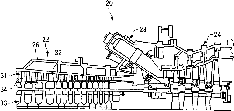
[0042] figure 1 It is a figure for demonstrating the schematic structure of the gas turbine 20 of this embodiment.

[0043] Such as figure 1 As shown, in the gas turbine 20 , an air inlet (not shown), a compressor 22 , a combustor 23 , and a turbine 24 are provided from the upstream side toward the downstream side of the air flow.

[0044] Air taken in from an air inlet (not shown) is compressed by a compressor 22 to become high-temperature, high-pressure compressed air, and is sent to a burner 23 . In the combustor 23 , gas such as natural gas or oil such as light oil or light heavy oil is supplied to the compressed air, and the fuel is combusted to generate high-temperature, high-pressure combustion gas. The high temperature, high pressure combustion gases are injected into the turbine 24 and expand within the turbine 24 to rotate the turbine 24 . The...


PUM


Abstract

An assembling method of a stator blade ring segment which can suppress the risks of thermal deformation and deterioration of strength, secure a degree of freedom of profile, and enhance the compression performance of a compressor. Furthermore, welding is provided in which a welding object can be prevented from floating from a groove or a recess at the time of welding, and welding can be carried out well. Sidewall portions (50b) on the opposite sides are formed to incline against the bottom (50a) so that the width of a groove (50) formed in each segment split body (41) decreases gradually fromthe outer circumferential side toward the bottom(50a). A coupling member (42) has such a cross-section that its width becomes largest at a protrusion (42b) located at an intermediate part in the thickness direction. When the coupling member (42) is placed in the groove (50), the protrusions (42b) on the opposite sides abut against or approach the sidewall portion (50b) of the groove (50), a space(100) is formed on the bottom (50a) side of the groove (50) and a groove (200) of substantially V-shaped cross-section is formed on the side away from the bottom (50a) of the groove (50).

Description

technical field [0001] The present invention relates to an assembly method of stator blade ring pieces constituting a stator blade ring of an axial flow compressor, a stator blade ring piece, a coupling part and the like. Background technique [0002] The stator blade ring of the axial flow compressor is configured by arranging a plurality of, for example, tens to hundreds of stator blades in the circumferential direction. [0003] In the past, the method of assembling the stator vane ring was often used, that is, the stator vane was inserted between the inner fender and the outer fender forming the compartment wall and temporarily assembled, and the stator vane was inserted from the inner fender and the outer fender. Electron beam welding is performed on the side surfaces of the plates in a circumferential shape to join both end portions of the stator blades to the inner baffle and the outer baffle (see Patent Documents 1 and 2). [0004] Patent Document 1: (Japanese) Japa...

Claims


Application Information

Patent Timeline
Patent Type & Authority Patents(China)
IPC IPC(8): F04D29/54
CPCF04D29/542F01D9/044F01D9/041F04D29/023F05D2230/232Y10T29/49323F04D29/38F04D29/44F04D29/54
Inventor 中村育生胁邦彦
Owner MITSUBISHI POWER LTD
Why Eureka
Try Eureka