
Packless fluid hydraulic cooling tower

A cooling tower, no filler technology, used in the field of no filler fluid cooling towers, can solve the problems of reducing the cooling tower heat dissipation performance, scaling and blocking of heat dissipation materials, etc.

Inactive Publication Date: 2010-01-06
SHANGHAI LIANGJI COOLING EQUIP CO LTD
View PDF0 Cites 0 Cited by
  • Summary
  • Abstract
  • Description
  • Claims
  • Application Information

AI Technical Summary

Problems solved by technology

[0003] However, the radiator is made of sheet-like heat sink material. After a period of use, there will be fouling and clogging on the heat sink material, which will reduce the heat dissipation performance of the cooling tower. Therefore, the scaling phenomenon on the heat sink material must be removed

Method used


Image

  • Packless fluid hydraulic cooling tower
  • Packless fluid hydraulic cooling tower
  • Packless fluid hydraulic cooling tower

Examples


Embodiment Construction

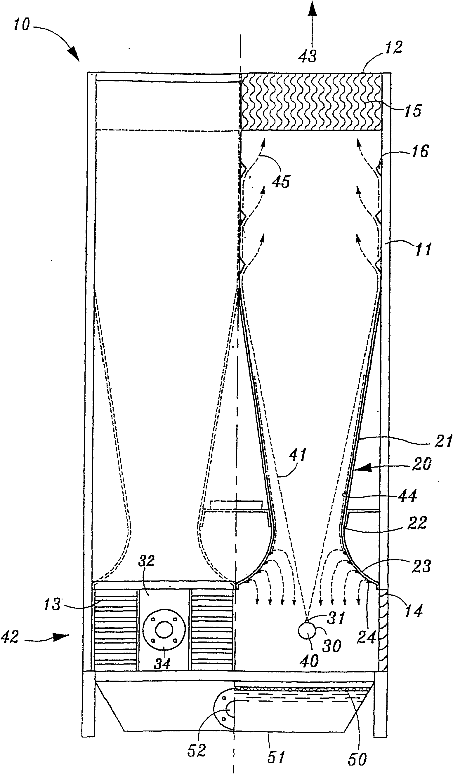
[0016] see figure 2 , 3 As shown, the fluid cooling tower 10 without packing of the present invention includes a tower body 11 , which is a structure made of plastic material or copper plate. The top of the tower body 11 has a hot air discharge port 12 . A cold air inlet 13 is arranged near the bottom of the tower body 11, so that the outside cold air enters. The Xinhua News Agency air inlet 13 is composed of Louvers blades 14, which are inclined from outside To introduce cold air 42. A plate 32 is disposed between the louver blades 14 .

[0017] The inside of the tower body 11 and above the cold air inlet 13 are provided with multiple sets of symmetrical diffusers 20 (DIFFUSER), each set of diffusers 20 is provided with a jet tube 30, and the radial outer wall of the jet tube 30 is provided with several The V-shaped nozzles 31 arranged equidistantly allow the hot liquid flowing into the spray pipe 30 to be ejected from the V-shaped nozzles 31 . One end of the spray pipe ...


PUM


Abstract

The invention relates to a packless fluid hydraulic cooling tower, which comprises a tower body. The inside of the tower body is provided with a spouting pipe and a diffuser; the top part of the tower body is provided with a water eliminator, and the periphery of lower end of the tower body is provided with cold air inlets; and a plurality of baffles are arranged above and on the lower edge of the diffuser. When hot liquid is upwards spouted from the spouting pipe in form of high speed fluid which is shaped into a continuous water curtain, the high speed fluid upwards flows along the outer wall surface of the diffuser and is veered after passing through the plurality of baffles arranged above, and then the veered fluid performs heat exchange with air in the region; when the hot liquid returning back along the outer wall surface of the diffuser is led to the baffles on the lower edge, the hot liquid is spouted evenly to be mixed and exchange heat with incoming cold air for improving the heat dispersion of the cooling tower.

Description

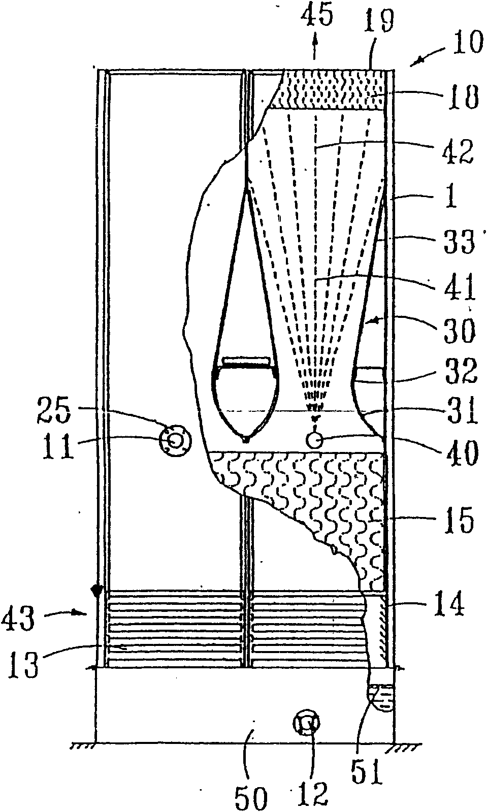
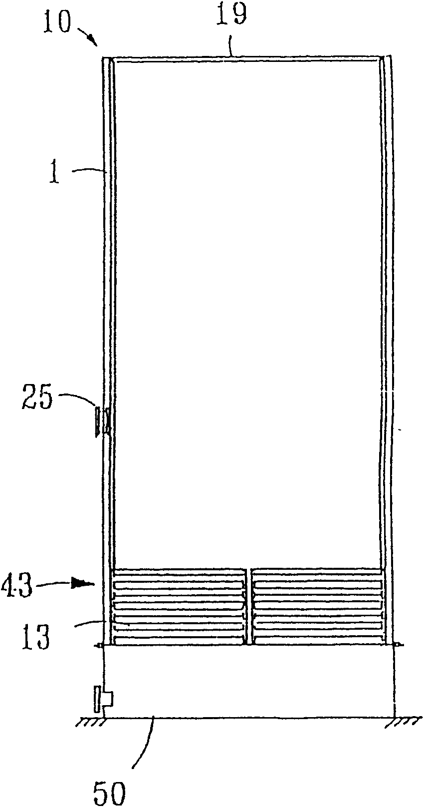
technical field [0001] The invention relates to a fluid cooling tower without filler, which is provided with several baffles above the diffuser and on the narrowing part of the diffuser, which can increase the amount of cooling air and change the flow direction of the liquid, thus improving the efficiency of the cooling tower. thermal performance. Background technique [0002] see Figure 1A and Figure 1B Shown, the inventor once proposed a kind of vertical fluid cooling tower on November 22, 1984 (certificate number No. 117483, hereinafter referred to as the previous case), this kind of structure is to make the hot liquid upwards from the jet tube to continuously Curtain-shaped high-speed spray, and spray into the throat of the diffuser, resulting in negative pressure below the throat of the diffuser, a large amount of external cooling air is sucked in from the air inlet below the tower to form an upward flow of air flow, so that the air flow in the same direction Mix an...

Claims


Application Information

Patent Timeline
IPC IPC(8): F28C3/06
Inventor 张恒钦
Owner SHANGHAI LIANGJI COOLING EQUIP CO LTD
Learn More