
Heat dissipating device and heat dissipating fin

a heat dissipating device and heat dissipating fin technology, which is applied in the direction of semiconductor devices, lighting and heating apparatus, tubular elements, etc., can solve the problems of increasing noise and undesirable lowering of the heat dissipating efficiency achieve the reduction of the flow field resistance the effect of reducing the weight of the heat dissipating device and reducing the amount of air

Active Publication Date: 2014-05-08
WISTRON CORP
View PDF15 Cites 2 Cited by
  • Summary
  • Abstract
  • Description
  • Claims
  • Application Information

AI Technical Summary

Benefits of technology

This patent describes a heat dissipating device that uses differently shaped fins to improve heat dissipation. The fins are arranged in a spaced-apart pattern, which reduces resistance and allows more air to flow through the device, resulting in better heat dissipation efficiency. Additionally, the fins have cut edges, which makes the device lighter and saves on material.

Problems solved by technology

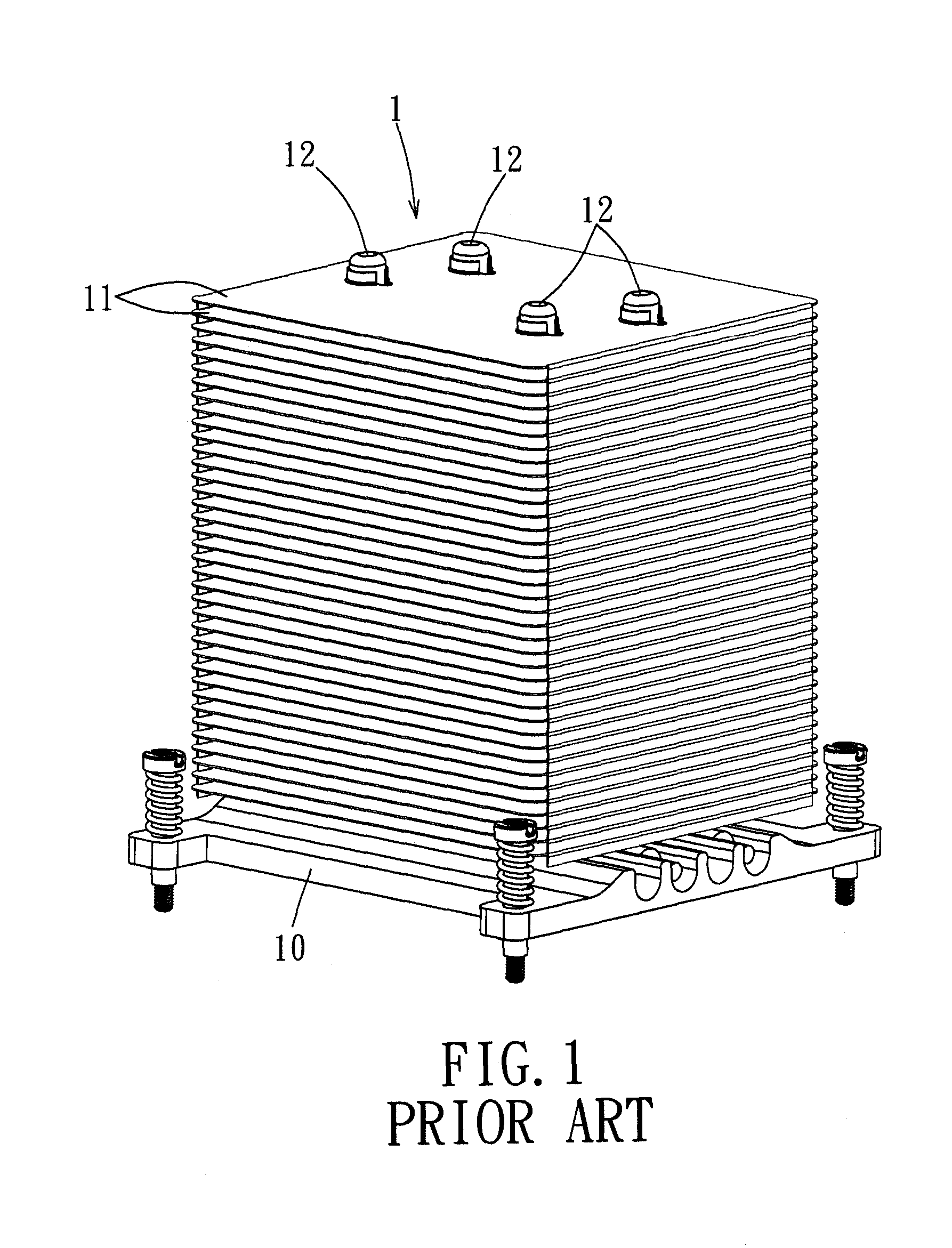
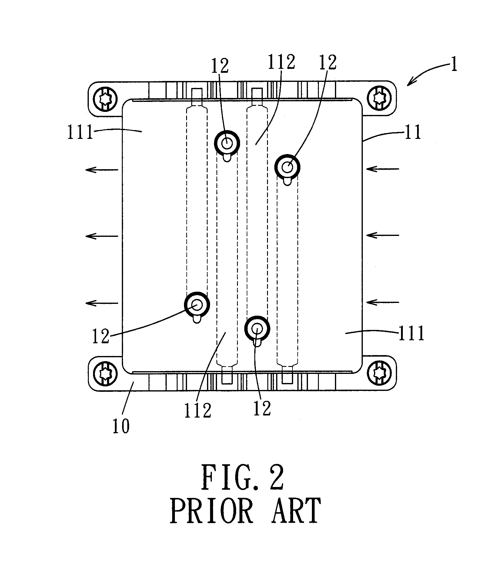
However, increasing the number and area of the heat dissipating fins will not only increase the overall weight of the heat dissipating device, the flow field resistance will also rise, so that the amount of airflow supplied by a heat dissipating fan will drop when the air passes through the heat dissipating device, which will undesirably lower the heat dissipating efficiency of the heat dissipating device.
However, raising the rotational speed of the fan will result in increased noise.

Method used


Image

  • Heat dissipating device and heat dissipating fin
  • Heat dissipating device and heat dissipating fin
  • Heat dissipating device and heat dissipating fin

Examples


Embodiment Construction

[0044]Before the present invention is described in greater detail, it should be noted that like elements are denoted by the same reference numerals throughout the disclosure.

[0045]Through a description of the preferred embodiments, the technical means employed by the present invention to achieve the intended objects, and the advantageous effects contemplated thereby, can be better understood and appreciated. It is noted that the accompanying drawings are for illustration and reference only, and are not intended to limit the scope of the present invention.

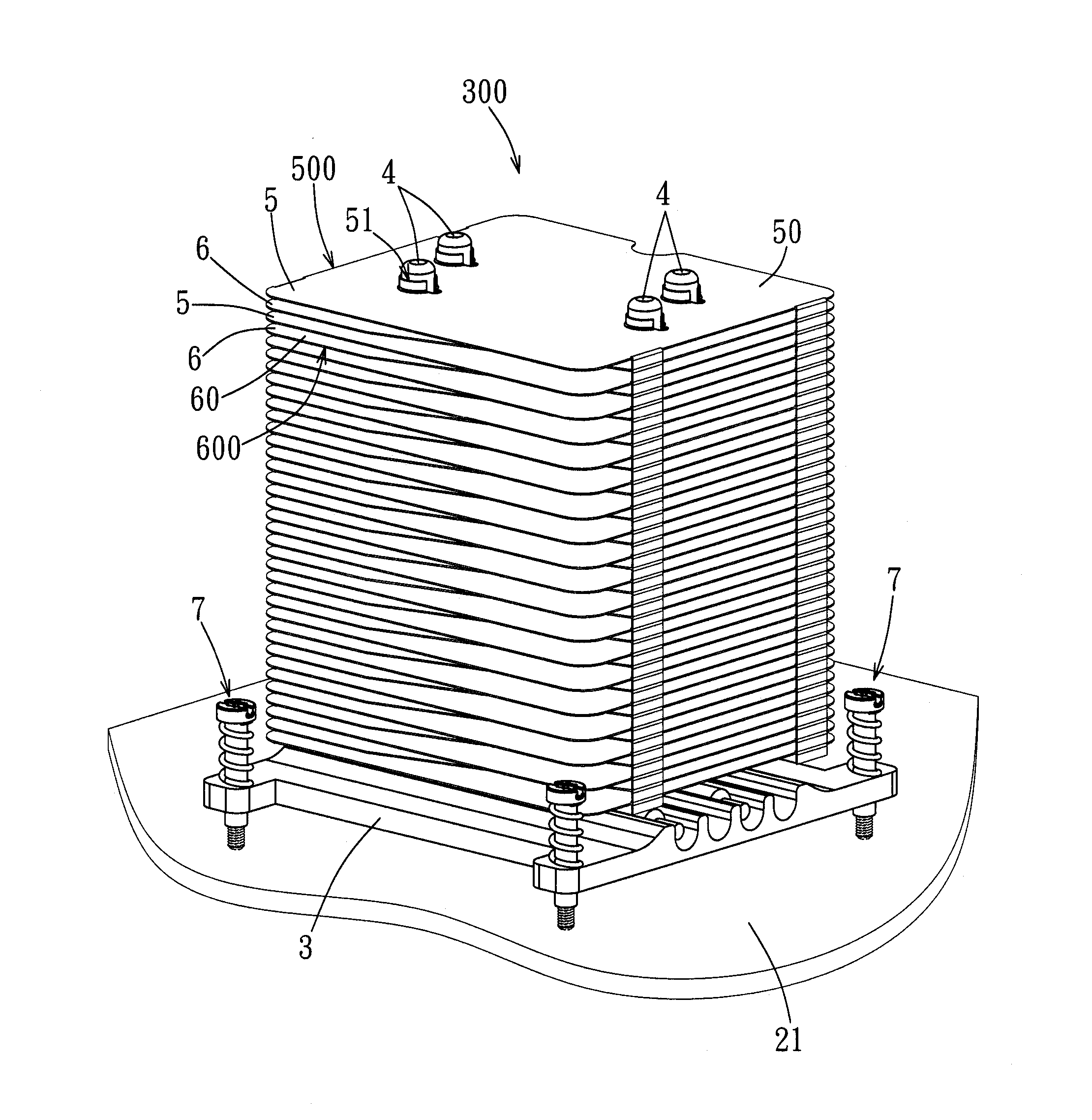
[0046]Referring to FIGS. 4 and 5, the first preferred embodiment of a heat dissipating device 300 according to the present invention is shown to be applied to a server. The heat dissipating device 300 is mounted on a motherboard 21 for dissipating the heat generated by a chip 211 on the motherboard 21. In this embodiment, the chip 211 is exemplified as a central processing unit.

[0047]As shown in FIGS. 5, 6, 7, and 8, the heat dissip...


PUM


Abstract

A heat dissipating device includes a base, a heat pipe disposed on the base, and a plurality of first and second heat dissipating fins. Each first heat dissipating fin includes a fin body having a first through hole for extension of the heat pipe therethrough. The first and second heat dissipating fins are mounted on the heat pipe in a stack and in a spaced-apart alternating arrangement. Each second heat dissipating fin includes a fin body having a second through hole for extension of the heat pipe therethrough, two adjacent lateral edges, and a cut edge interconnecting the lateral edges such that each second heat dissipating fin has a smaller area than each first heat dissipating fin. Thus, the flow field resistance of the heat dissipating device can be reduced to increase the amount of airflow through the heat dissipating device for enhancing the heat dissipating efficiency.

Description

CROSS-REFERENCE TO RELATED APPLICATION[0001]This application claims priority of Taiwanese Application No. 098219983, filed on Oct. 29, 2009.BACKGROUND OF THE INVENTION[0002]1. Field of the Invention[0003]The invention relates to a heat dissipating device and heat dissipating fins thereof, more particularly to a heat dissipating device having heat dissipating fins of different shapes which are stacked in a spaced-apart and alternating arrangement.[0004]2. Description of the Related Art[0005]Since an electronic component (such as a central processing unit or operating chip) in a computer system operates at an increased speed, the heat generated thereby also increases. In order to effectively enhance the heat dissipating efficiency of a heat dissipating device, some methods of improvement are to increase the number and area of heat dissipating fins of the heat dissipating device. However, increasing the number and area of the heat dissipating fins will not only increase the overall wei...

Claims


Application Information

Patent Timeline
Patent Type & Authority Applications(United States)
IPC IPC(8): F28D15/02
CPCF28D15/02F28D15/0275F28F1/32H01L23/3672H01L23/4006H01L23/427H01L23/467H01L2924/0002H01L2924/00
Inventor CHAO, YEN-YUWU, MING-CHANGTIEN, MING-WEI
Owner WISTRON CORP
Learn More