Multifunctional connecting support

A multifunctional, supporting body technology, applied in the direction of supporting, clamping, positioning devices, etc., can solve the problems of inability to assemble, inability to locate and connect other components, single function, etc., and achieve the effect of increasing the space for conversion and adjustment

Inactive Publication Date: 2010-01-13
SHENYANG AIRCRAFT CORP
View PDF0 Cites 6 Cited by
  • Summary
  • Abstract
  • Description
  • Claims
  • Application Information

AI Technical Summary

Problems solved by technology

[0002] In the process of selecting hole system components to assemble fixtures, it is often encountered inconvenient situations such as conversion, adjustment, orientation, positioning, and pin tightening, which cause problems such as cumbersome fixture structures and inconvenient clamping of workpieces; Each standard component in the first eight types of component systems has a single function, and can only be connected and combined in one direction, and its side cannot be positioned and connected with other components; when more than two technical elements need to be solved, they must be transitioned through supports Plates, screw hole transition plates, support steering plates, positioning plates and other components indirect layer-by-layer conversion, bedding, lifting and other auxiliary means to achieve the ultimate goal. For fixtures that need to be flipped, there is no conversion mechanism in many components, so they cannot be assembled

Method used


Image

  • Multifunctional connecting support
  • Multifunctional connecting support
  • Multifunctional connecting support

Examples


Embodiment Construction

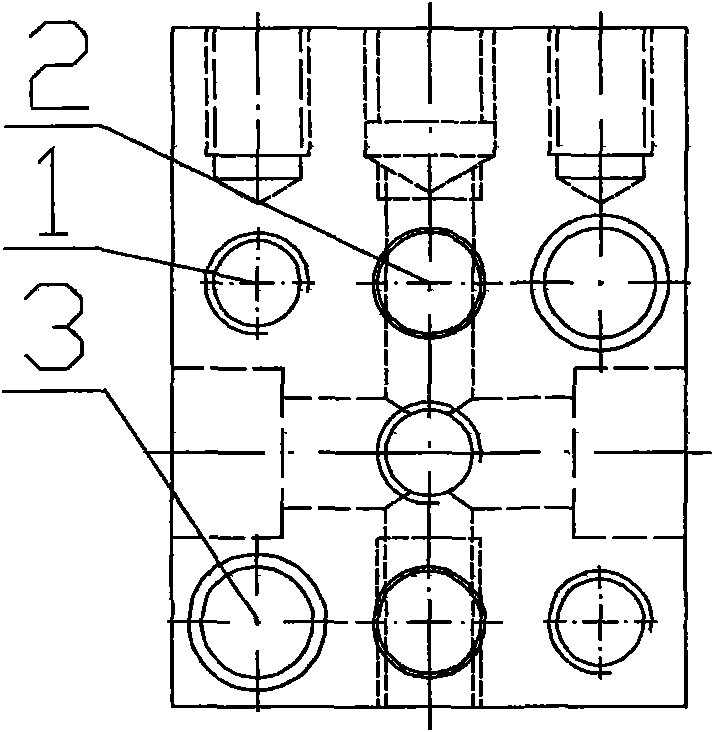
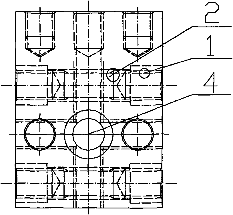
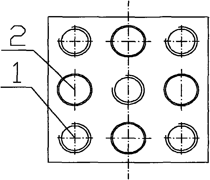
[0010] The multifunctional connection support includes a support body, which is characterized in that the support body is a rectangular parallelepiped, and the dimensions of the rectangular parallelepiped are 60mm, 60mm, and 80mm, and an M12, 80mm deep is made upward at the center of a short side 60mm and short side 60mm. Threaded through hole, on the plane axis of another short side 60mm and short side 60mm, make four Φ12H7 pin shaft blind holes with a distance of 40±0.01mm and a depth of 15mm in four directions, and four on the diagonal Make four M12 threaded blind holes with a distance of 40±0.01mm and a depth of 15mm in the direction, and make two distances on the axis of the upper and lower directions on the two symmetrical surfaces of 60mm on the short side and 80mm on the long side. For the 40±0.01mm pin shaft through hole, one M12 inner hexagon screw hole is made on the upper right side of the axis and the lower left side of the axis, and one M12, 15mm deep hole is made...


PUM


Abstract

The invention discloses a multifunctional connecting support which is a multifunctional element used in a hole-series modular fixture. A supporting body is made into a cubiod, and a thread through hole is made on the center of the surface formed by two short edges, the axis of the surface formed by other two short edges is manufactured with four pin shaft blind holes, and four thread blind holes are manufactured on the diagonal; two pin shaft through holes are respectively manufactured on the axis of the symmetrical surfaces of the two short edges and long edges; an inner hexagon screw passing hole is respectively manufactured above the right side of the axis and below the left side of the axis, and the thread blind hole is respectively manufactured above the left side of the axis, below the right side of the axis and on the center; a bolt sinking through hole is manufactured on the axis crossing point of the symmetrical surface of the other two short edges and long edges, and a pin shaft blind hole is respectively manufactured on two ends of a horizontal axis. The invention has the advantages: due to adoption of hexagonal support, the invention is capable of extending to multiple directions to be combined with other hole system elements and realize the functions of orientation, positioning, limiting and locking; and space for converting and adjusting to each angel with 90 degrees can be added.

Description

Technical field: [0001] The invention is a multi-functional element used in hole system combination fixtures. Background technique: [0002] In the process of selecting hole system components to assemble fixtures, it is often encountered inconvenient situations such as conversion, adjustment, orientation, positioning, and pin tightening, which cause problems such as cumbersome fixture structures and inconvenient clamping of workpieces; Each standard component in the first eight types of component systems has a single function, and can only be connected and combined in one direction, and its side cannot be positioned and connected with other components; when more than two technical elements need to be solved, they must be transitioned through supports Plates, screw hole transition plates, support steering plates, positioning plates and other components indirect layer-by-layer conversion, bedding, lifting and other auxiliary means to achieve the ultimate goal. For fixtures tha...

Claims


Application Information

Patent Timeline
Patent Type & Authority Applications(China)
IPC IPC(8): B23Q3/00
Inventor 王金财王环文靖
Owner SHENYANG AIRCRAFT CORP
Why Eureka
Try Eureka