Multifunctional material mechanics testing machine with functions of tension torsion and pressure torsion

A material mechanics and multi-functional technology, applied in the direction of applying stable torsion to test the strength of materials, analyzing materials, scientific instruments, etc., can solve the problem that the real test data of tension and compression torsion cannot be obtained, and the lack of tension and compression torsion test functions And other issues

Inactive Publication Date: 2010-01-13
孙仙山 +1
View PDF0 Cites 49 Cited by
  • Summary
  • Abstract
  • Description
  • Claims
  • Application Information

AI Technical Summary

Problems solved by technology

[0002] At present, the existing material mechanics testing machines can only perform tests such as tension, compression, bending torsion, torsion, cantilever beam bending, simply supported beam bending, etc., lacking the functions of tension torsion and compre

Method used


Image

  • Multifunctional material mechanics testing machine with functions of tension torsion and pressure torsion
  • Multifunctional material mechanics testing machine with functions of tension torsion and pressure torsion
  • Multifunctional material mechanics testing machine with functions of tension torsion and pressure torsion

Examples


Embodiment 1

[0019] Example 1 Tensile torsion test

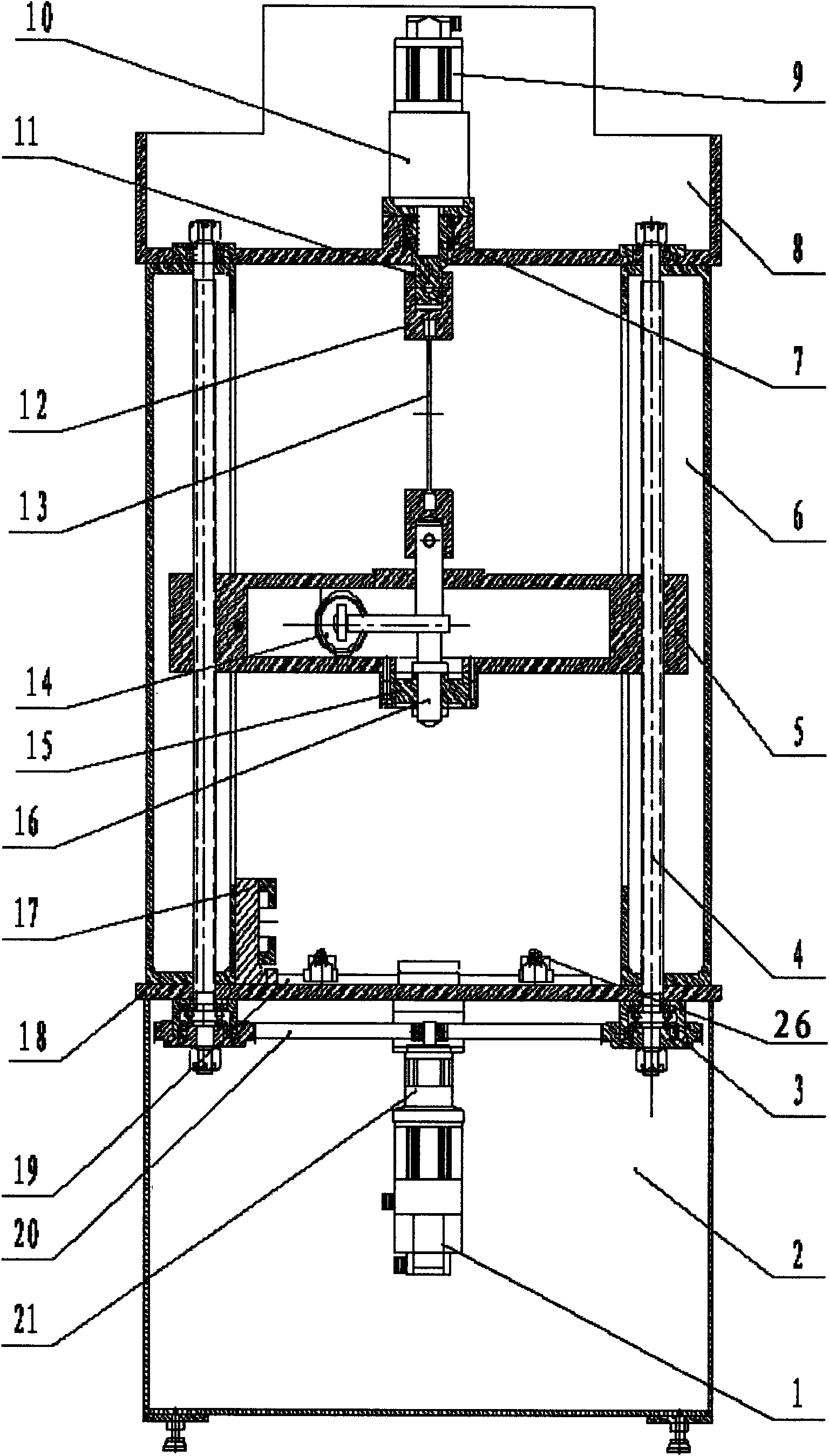
[0020] The multi-functional material mechanics testing machine reference of this embodiment has tension torsion and compression torsion functions figure 1 , form a fixed frame by casing 2, workbench 18, column 6 of left and right two hollow cores, upper beam 8. Leading screw 4 passes workbench 18, column 6, middle beam 5 and upper beam 8, and the fixing mode of leading screw 4 two ends makes it can rotate around the axis of self and can not move up and down. The leading screw 4 is connected with the middle beam 5 by threads. After the lifting motor 1 is decelerated by the lifting reducer 21, the synchronous belt 20 drives the left and right two synchronous pulleys 3 to rotate, and the two synchronous pulleys 3 drive the left and right two lead screws 4 to rotate. After the motor 1 is decelerated by the lifting reducer 21, under the control of the electric control mechanism, the lead screw 4 can be rotated slowly at a speed below 0.1 r / ...

Embodiment 2

[0023] Example 2 Compression torsion test

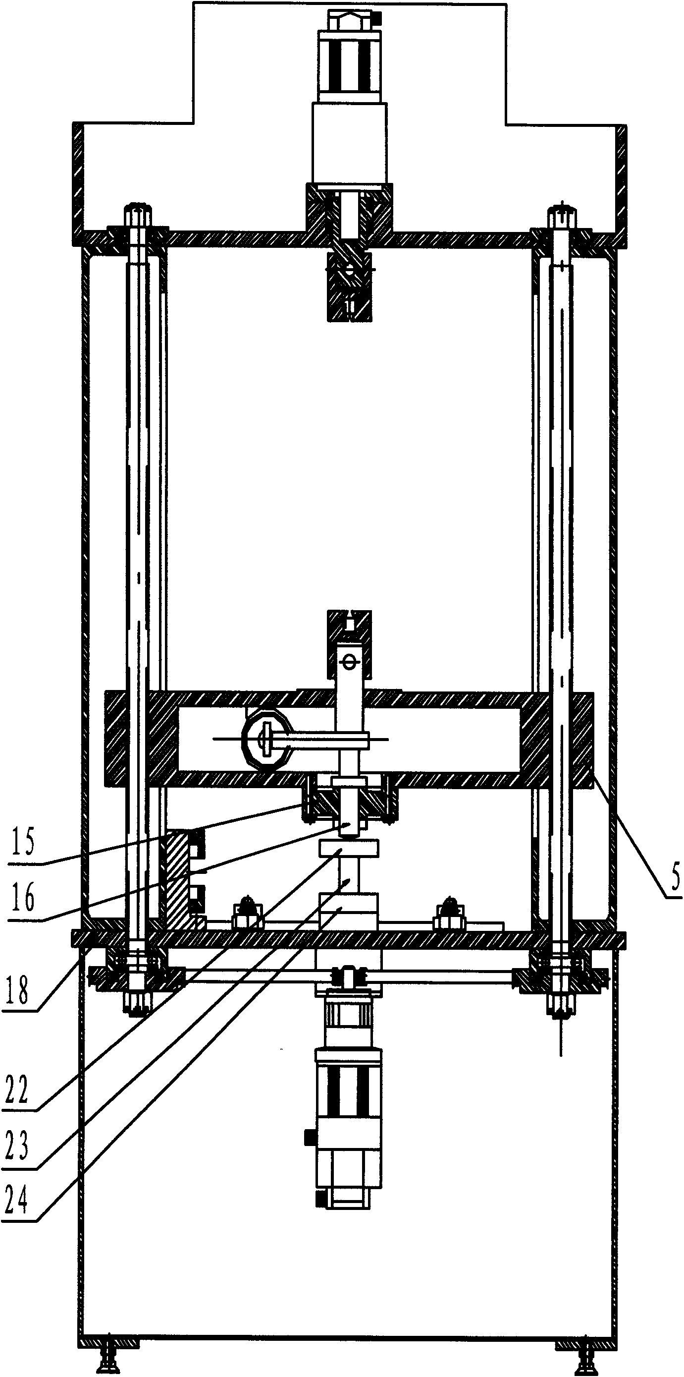
[0024] The difference between this embodiment and embodiment 1 is that starting the lifting motor 1 drives the middle beam 5 to move upward at a slow speed, and at the same time, the torsion motor 9 drives the hanging column 11 to rotate at a slow speed, so that the compression torsion test can be carried out.

Embodiment 3

[0025] Example 3 Tensile Test

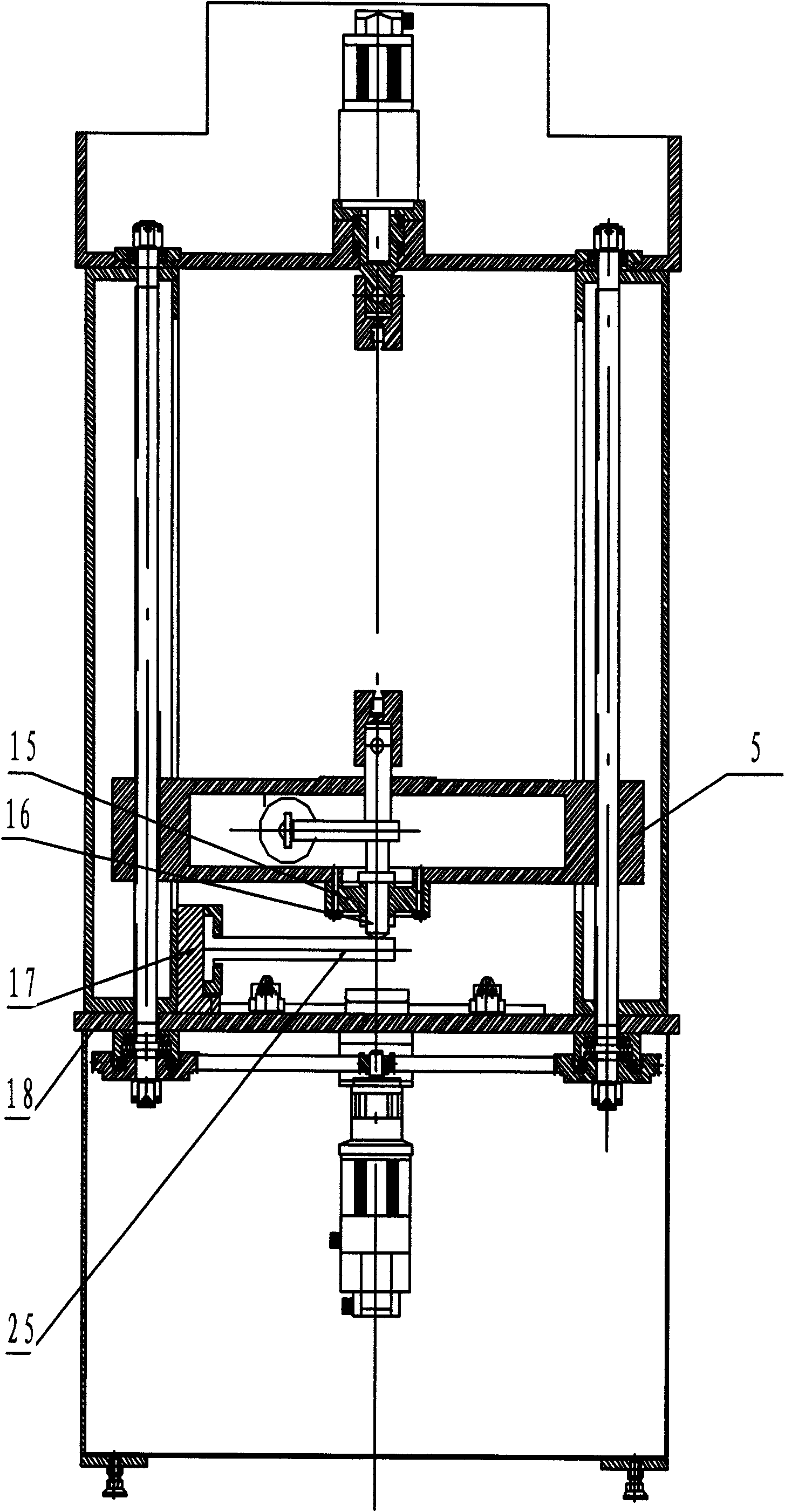
[0026] The difference between this embodiment and embodiment 1 is that only the lifting motor 1 is started to move the middle crossbeam 5 slowly downwards, the torsion motor 9 is not started, the test piece 13 is stretched or even broken after being stressed, and the pulling and pressing rod 16 will pull the tension The data is transmitted to the tension and pressure sensor 15, and the tension and pressure sensor 15 senses the magnitude of the tension and sends the data to a computer for data processing and image display.


PUM


Abstract

The invention relates to a material mechanics testing machine, belonging to the technical field of the material mechanics testing machine. The material mechanics testing machine is characterized in that the upper end and the lower end of the stander are provided with a lift motor and a torsion motor; the two motors form into one set of dynamic loading system and are controlled as well as coordinated to realize a tension torsion test and a pressure torsion test by an external electrical control system; a guide screw is arranged between the work table and an upper beam, wherein the upper end of the guide screw is fixed at the upper bean, and the lower end of the guide screw is driven by a synchronous belt wheel in a connection way; a middle beam is arranged between the work table and the upper beam; the middle beam is respectively provided with a tension compression rod and a tension compression sensor as well as a torsion sensor, wherein the tension compression sensor and the torsion sensor are communicated with a computer; the upper part of the wok table is provided with a slide way with a slide pillow; one side of the work table, near the vertical rod, is provided with a support seat; and the lower part of a torsion reduction machine is fixedly provided with a hanging rod, wherein the lower part of the hanging rod is provided with a clamp head. The two motors in the one set of dynamic loading system are simultaneously coordinated and controlled by the electrical control system to realize the functions of tension torsion and pressure torsion, and the rotate speeds of the two motors are adjusted by the electrical control system to meet the requirement of different experiments, digitally process the collection and the transmission of a parameter to be tested, and truly and exactly display the parameter on a screen.

Description

1. Technical field [0001] The invention relates to a material mechanics testing machine, which belongs to the technical field of material mechanics testing machine structure. 2. Background technology [0002] At present, the existing material mechanics testing machines can only perform tests such as tension, compression, bending torsion, torsion, cantilever beam bending, simply supported beam bending, etc., lacking the functions of tension torsion and compression torsion tests, when the tensile and torsion tests are required When it is carried out simultaneously, it can only be tested separately, and then theoretically deduced, and the real test data of tension torsion and compression torsion cannot be obtained. 3. Contents of the invention [0003] The object of the present invention is to solve the deficiencies in the above-mentioned prior art, and to provide a test that can not only carry out tests such as tension, compression, bending, torsion, cantilever beam bending,...

Claims


Application Information

Patent Timeline
IPC IPC(8): G01N3/00G01N3/22
Inventor 孙仙山孙芳山
Owner 孙仙山
Why Eureka
Try Eureka