Backlight module and optical plate thereof

A backlight module and optical board technology, applied in optics, optical components, nonlinear optics, etc., can solve the problems of increasing light transmission interface loss, increasing the number of light interfaces, reducing light utilization rate, etc., to improve light utilization rate, Avoid the effect of light source afterimage and interface loss

Inactive Publication Date: 2010-01-13
HONG FU JIN PRECISION IND (SHENZHEN) CO LTD +1
View PDF0 Cites 5 Cited by
  • Summary
  • Abstract
  • Description
  • Claims
  • Application Information

AI Technical Summary

Problems solved by technology

[0005] However, when the light is transmitted in the prism sheet 10 and the upper diffusion sheet 14, part of the light will be abso

Method used


Image

  • Backlight module and optical plate thereof
  • Backlight module and optical plate thereof
  • Backlight module and optical plate thereof

Examples


Embodiment Construction

[0016] The backlight module and its optical board of the present invention will be further described in detail below with reference to the drawings and embodiments.

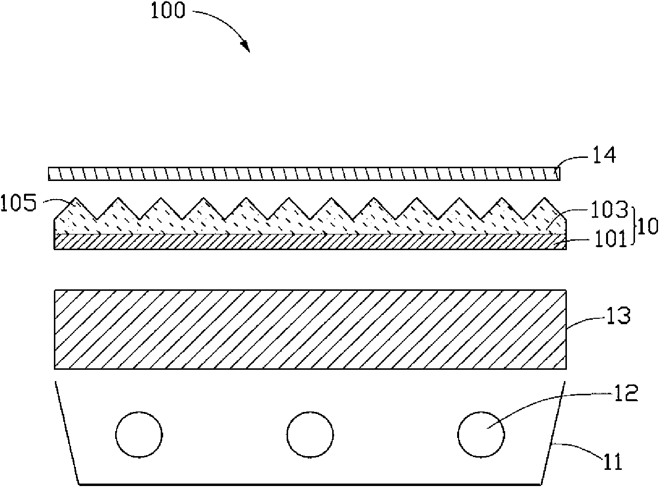
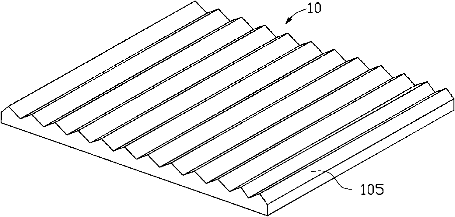
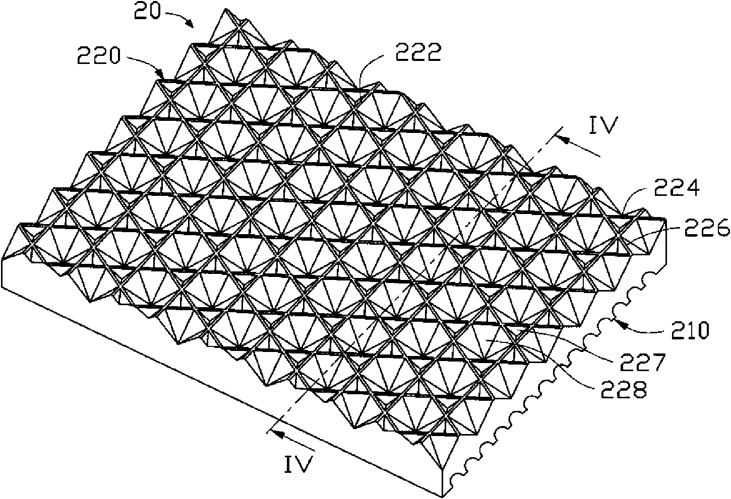
[0017] See image 3 and Figure 4 , shows an optical plate 20 according to a preferred embodiment of the present invention, which is composed of a transparent body, and the transparent body includes a first surface 210 and a second surface 220 opposite to the first surface 210 . The first surface 210 has a plurality of elongated arc-shaped grooves 212 parallel to each other. The second surface 220 has a plurality of triangular pyramid grooves 227 and a plurality of hexagonal pyramid grooves 228 , wherein each triangular pyramid groove 227 is surrounded by three adjacent hexagonal pyramid grooves 228 .

[0018] A plurality of elongated arc-shaped grooves 212 on the first surface 210 are arranged in a parallel linear array. The section of each elongated arc-shaped groove 212 along the vertical direction is arc-s...


PUM

PropertyMeasurementUnit
Center distanceaaaaaaaaaa
Depthaaaaaaaaaa

Abstract

An optical plate comprises a transparent body which comprises a first surface and a second surface opposite to the first surface; wherein, the first surface is provided with a plurality of mutually parallel long strip arc grooves; the second surface is provided with a plurality of triangular pyramid shaped grooves and hexagonal pyramid shaped grooves; each triangular pyramid shaped groove is enclosed by three adjacent hexagonal pyramid shaped grooves. A backlight module has the advantages of improving effective utilization ratio of light and enjoying uniformity of light emission. The invention also provides the backlight module adopting the optical plate.

Description

technical field [0001] The invention relates to a backlight module and its optical board. Background technique [0002] See figure 1 , shows a conventional direct-lit backlight module 100, which includes a frame 11, a plurality of light sources 12 disposed inside the frame 11, and a diffusion plate 13 disposed above the light sources 12 and covering the frame 11. [0003] In use, the light generated by the plurality of light sources 12 can be diffused after entering the diffuser plate 13 . However, after being diffused by the diffuser plate 13, the angles at which light emerges from the diffuser plate 13 become more chaotic, so that its brightness in a specific viewing angle range is not high; It is still often difficult for the plate 13 to directly diffuse the light from the light source 12 evenly, so that the light emitted from the diffuser plate 13 is prone to light source afterimages, that is, areas with different light intensity. [0004] In order to improve the brig...

Claims


Application Information

Patent Timeline
IPC IPC(8): G02B6/00G02F1/13357
Inventor 章绍汉
Owner HONG FU JIN PRECISION IND (SHENZHEN) CO LTD
Why Eureka
Try Eureka