U-type double-pin linear ultrasonic motor vibrator

A linear ultrasonic motor and vibrator technology, applied in the direction of generators/motors, piezoelectric effect/electrostrictive or magnetostrictive motors, electrical components, etc., can solve the problem of low electromechanical coupling efficiency and mechanical output capacity of piezoelectric ultrasonic motors Constraints, poor mechanical output capabilities, etc., to achieve the effect of simple structure, high electromechanical coupling efficiency, and increased amplitude and vibration speed

Inactive Publication Date: 2010-01-13
HARBIN INST OF TECH
View PDF0 Cites 5 Cited by
  • Summary
  • Abstract
  • Description
  • Claims
  • Application Information

AI Technical Summary

Problems solved by technology

[0004] In order to solve the problem that the mechanical output capability of the stator of the ultrasonic motor that is excited by pasting the piezoelectric ceramic sheet with the metal elastic body is restricted, the present invention provides a U-shaped biped linear ultrasonic motor vibrator
[0006] The piezoelectric ceramic element in the U-shaped double-legged linear ultrasonic motor vibrator of the present invention adopts a sandwich structure, and adopts piezoelectric ceramics with high electromechanical coupling efficiency d 33 mode work, which solves the problem of low electromechanical coupling efficiency and poor mechanical output capability of pasted piezoelectric ceramic chip piezoelectric ultrasonic motor

Method used


Image

  • U-type double-pin linear ultrasonic motor vibrator
  • U-type double-pin linear ultrasonic motor vibrator
  • U-type double-pin linear ultrasonic motor vibrator

Examples


specific Embodiment approach 1

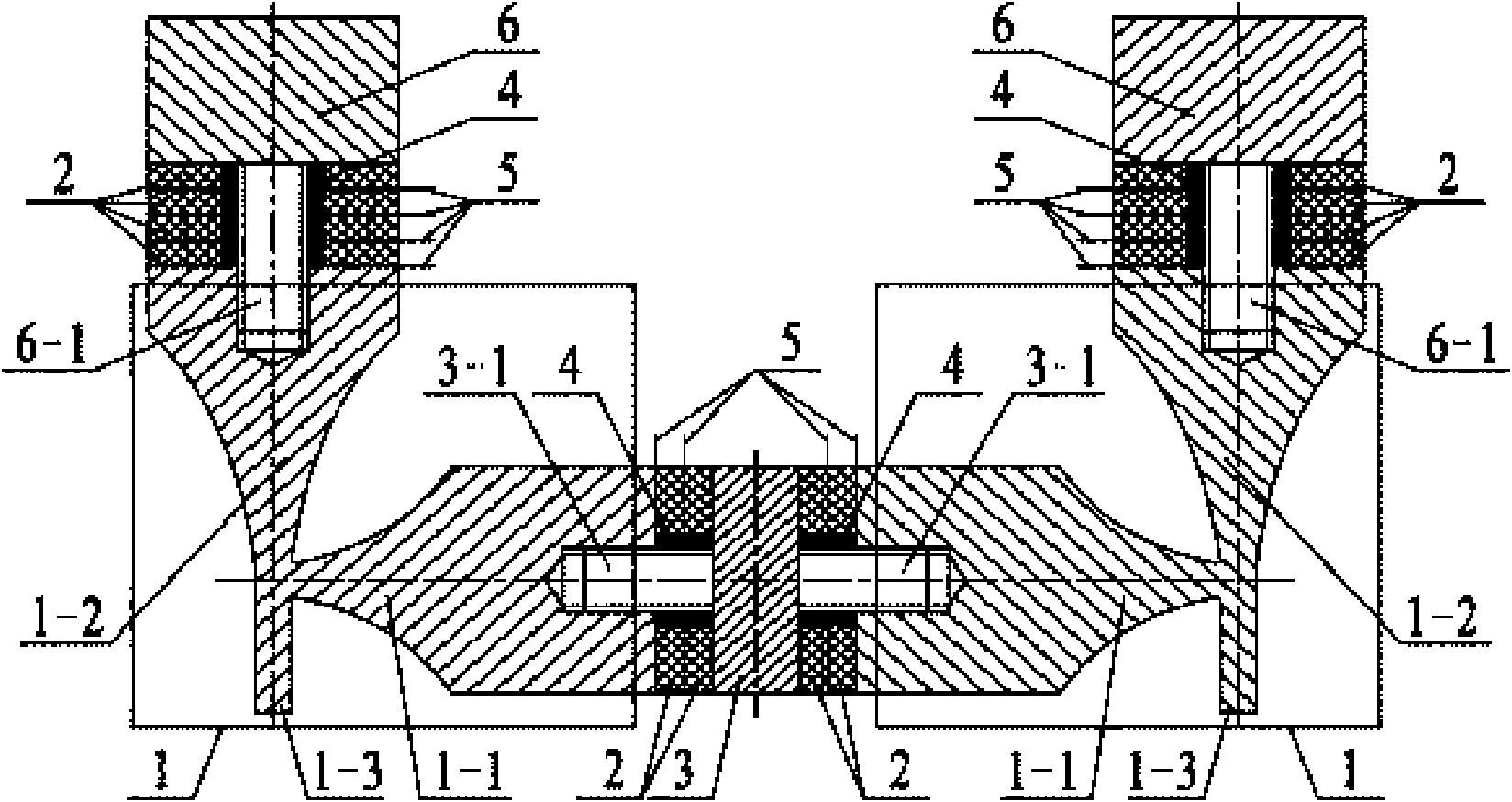
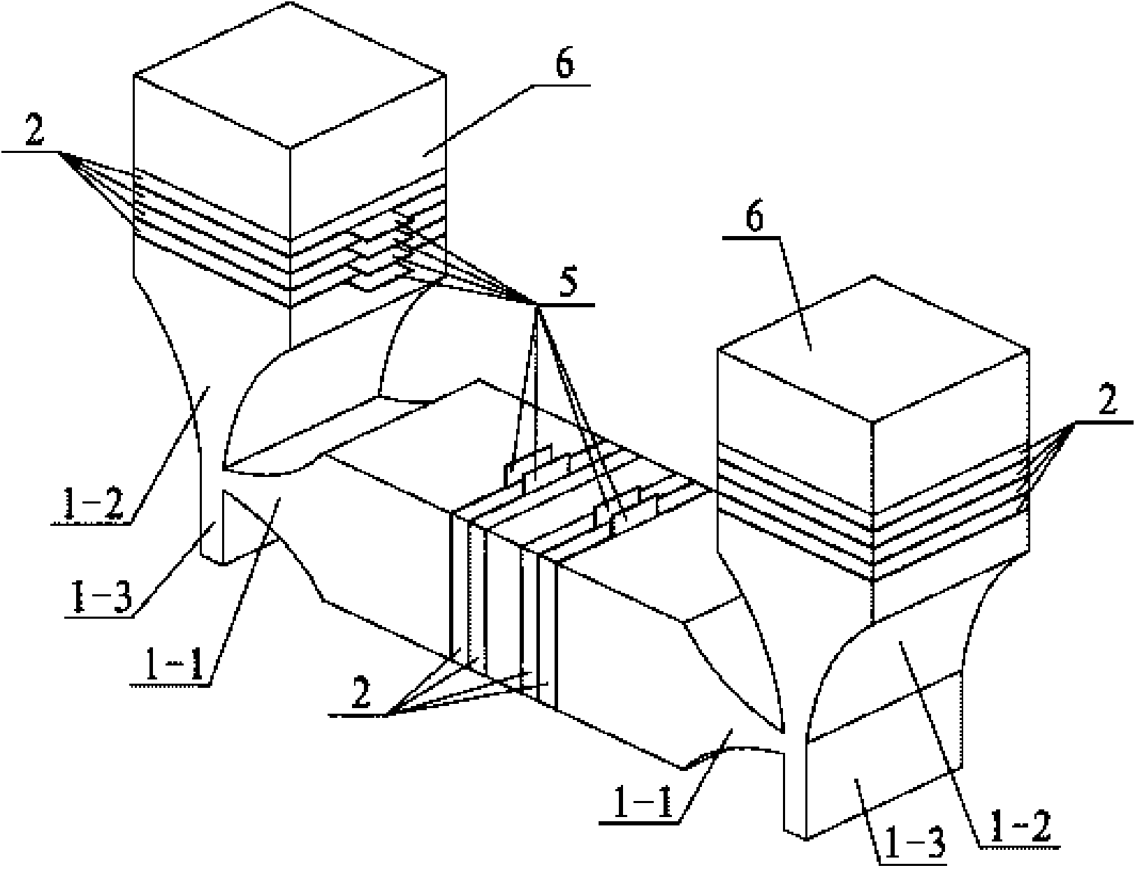
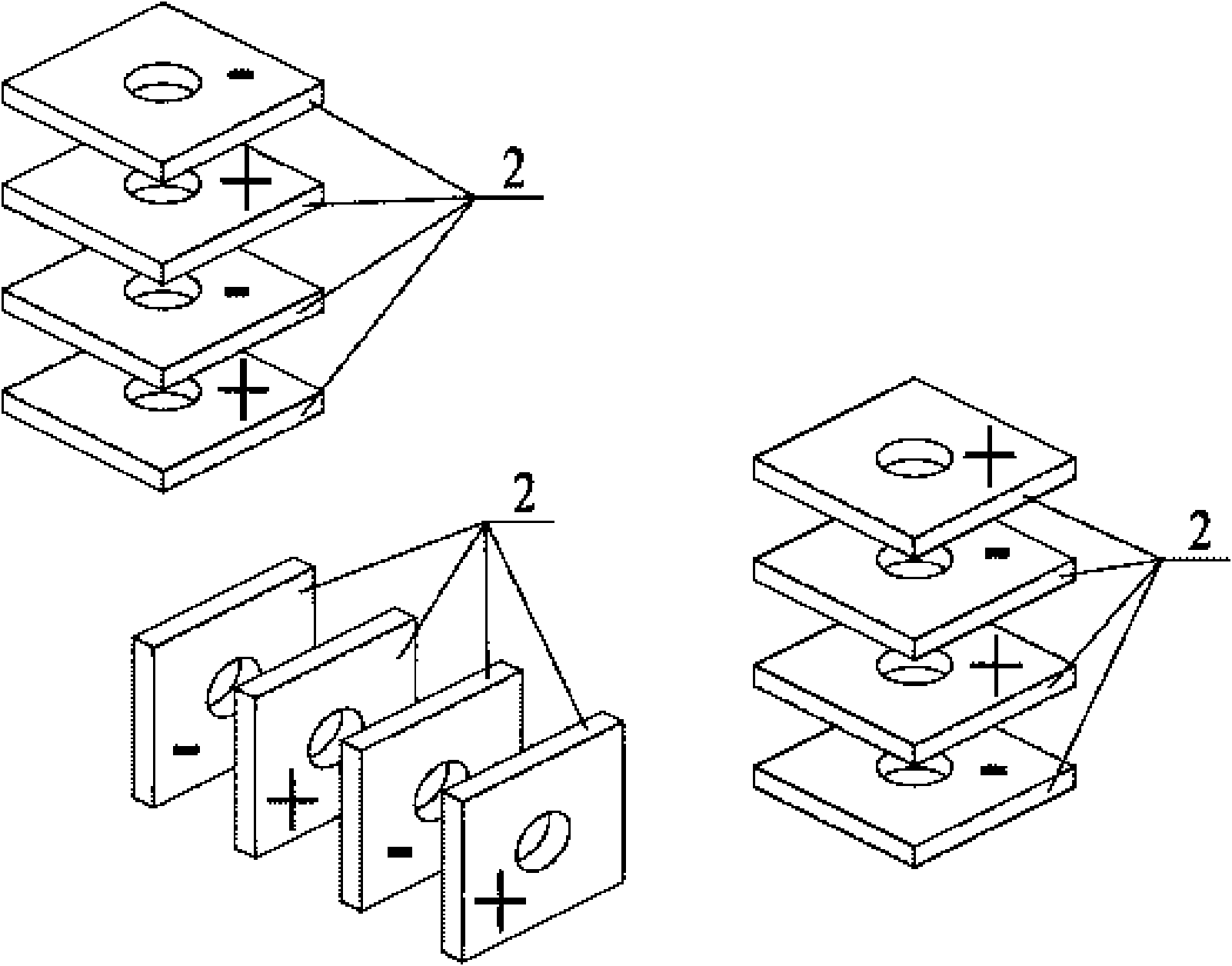
[0010] Specific implementation mode 1: Combination Figure 1 to Figure 4 To illustrate this embodiment, the U-shaped biped linear ultrasonic motor vibrator in this embodiment includes two connecting end covers 1, twelve piezoelectric ceramic plates 2, a flange 3, four insulating sleeves 4, and twelve pieces The electrode sheet 5 and two independent end caps 6; the connecting end cap 1 includes a vertical horn 1-2, a horizontal horn 1-1 and a driving foot 1-3, a vertical horn 1-2 and The horizontal horns 1-1 are all quadrangular prisms with a rectangular cross-section and tapering. The large end faces of the vertical horns 1-2 and the horizontal horns 1-1 have a blind with internal thread. The driving foot 1-3 is a rectangular parallelepiped, the upper end surface of the driving foot 1-3 is connected with the small end surface of the vertical horn 1-2, and the upper side of the driving foot 1-3 is connected with the horizontal horn 1- 2 is connected with the small end faces, th...

specific Embodiment approach 2

[0012] Embodiment 2: The difference between this embodiment and the U-shaped biped linear ultrasonic motor vibrator described in Embodiment 1 is that the cross-sections of the piezoelectric ceramic sheet 2 and the rear cover 3 are square or circular.


PUM


Abstract

The invention relates to a U-type double-pin linear ultrasonic motor vibrator, which relates to the field of piezoelectric ultrasonic motors and solves the problem of limited output capability of the prior mechanism. The U-type double-pin linear ultrasonic motor vibrator is characterized in that a vertical horn and a horizontal horn which are connected with end covers are of quadrangular prisms having rectangular sections and gradually thinning; big end faces of the vertical horn and the horizontal horn are provided with blind holes; driving pins are cuboids, the upper end faces of the driving pins are connected with a small end face of the vertical horn, and the upper parts of the side faces of the driving pins are connected with a small end face of the horizontal horn; flanges are provided with double-screw bolts which are fixedly connected with the blind holes and are sleeved with two pieces of piezoelectric ceramic plates; two independent end covers have the same structure and comprise double-screw bolts which are fixedly connected with the blind holes and are sleeved with four pieces of piezoelectric ceramic plates; all the piezoelectric ceramic plates are polarized along the thickness direction, the polarization directions of adjacent piezoelectric ceramic plates are opposite to each other, and electrode slices are arranged on positions applying driving signals; and the double-screw bolts of the flanges and the independent end covers are sleeved with insulation bushes. The invention is applied to the field of motors and has the advantages of high electromechanical coupling efficiency and large momental output.

Description

Technical field [0001] The invention relates to a U-shaped biped linear ultrasonic motor vibrator, belonging to the technical field of piezoelectric ultrasonic motors. Background technique [0002] The piezoelectric ultrasonic motor uses the inverse piezoelectric effect of piezoelectric ceramics to excite vibrations in the ultrasonic frequency range in the elastic body, and form a particle movement with a specific track at a specific point or a specific area on the surface of the elastic body, and then pass through the stator, The frictional coupling between the rotors converts the microscopic motion of the particle into the macroscopic motion of the rotor. It has the advantages of low speed and large torque, no transmission mechanism, no electromagnetic interference, fast response speed and self-locking when power off. As a piezoelectric drive, it has the advantages Very wide application. [0003] Due to the simplicity of the excitation principle and the simplicity of the theoret...

Claims


Application Information

Patent Timeline
Patent Type & Authority Applications(China)
IPC IPC(8): H02N2/04
Inventor 陈维山刘英想石胜君刘军考
Owner HARBIN INST OF TECH
Why Eureka
Try Eureka