Workpiece to be spot-welded

A workpiece and spot welding technology, applied to the edge of workpieces, manufacturing tools, welding equipment, etc., can solve problems such as difficult quality management, reduced strength, and poor identification.

Inactive Publication Date: 2010-01-13
HONDA MOTOR CO LTD
View PDF1 Cites 3 Cited by
  • Summary
  • Abstract
  • Description
  • Claims
  • Application Information

AI Technical Summary

Problems solved by technology

[0005] In the above-mentioned concave portion, if the depth or area is increased, the strength of the portion will be reduced, so there is usually a disadvantage of poor visibility.
In addition, depending on the equipment and sequence of the welding process in the factory, welding may be performed from the cabin side and welding may be performed from the outside of the vehicle. Therefore, there is also a problem that quality control of spot welding is difficult.

Method used


Image

  • Workpiece to be spot-welded
  • Workpiece to be spot-welded
  • Workpiece to be spot-welded

Examples


Embodiment Construction

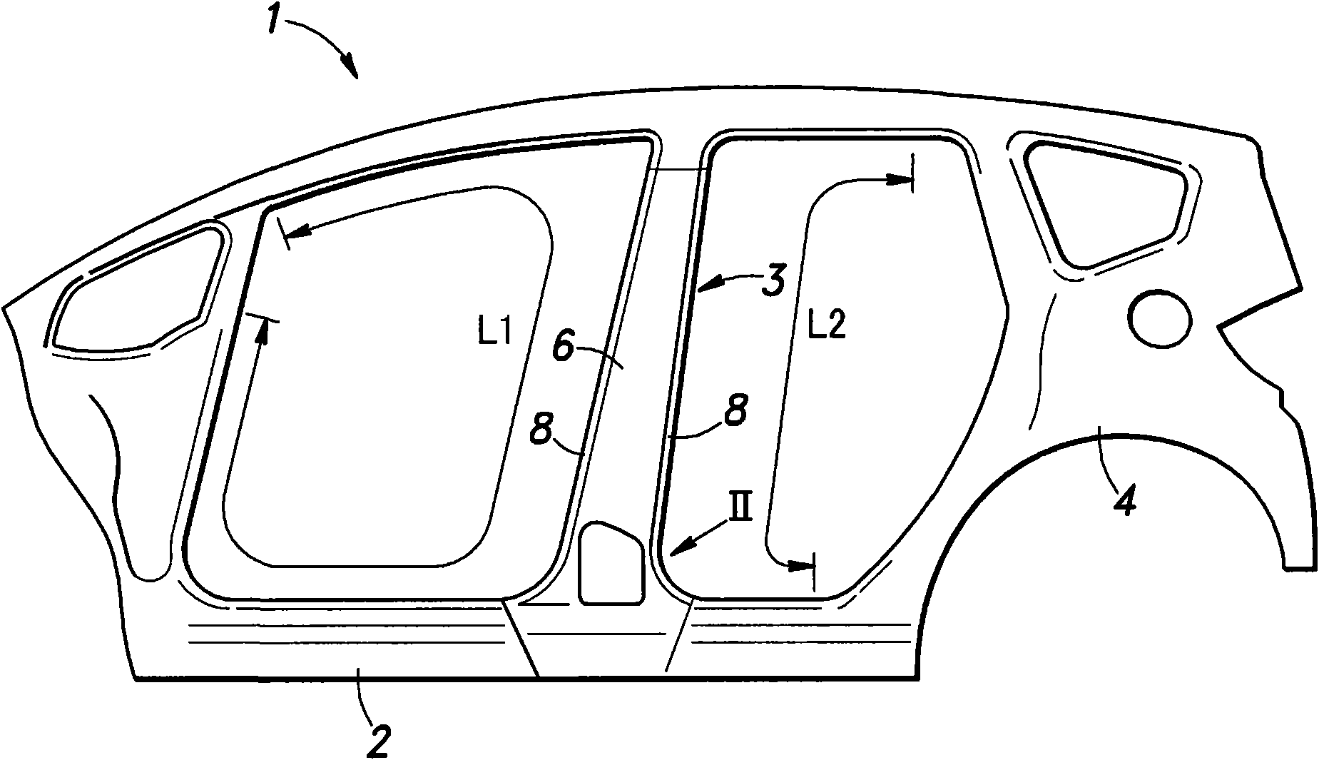
[0026] Embodiments of the present invention will be described below with reference to the drawings. Such as figure 1 As shown, a side sill 2 extending in the front-rear direction of the vehicle body is provided at the side of the vehicle body 1 at its lower portion. The illustrated example is a four-door vehicle, and a center pillar 3 is provided between the front and rear door openings.

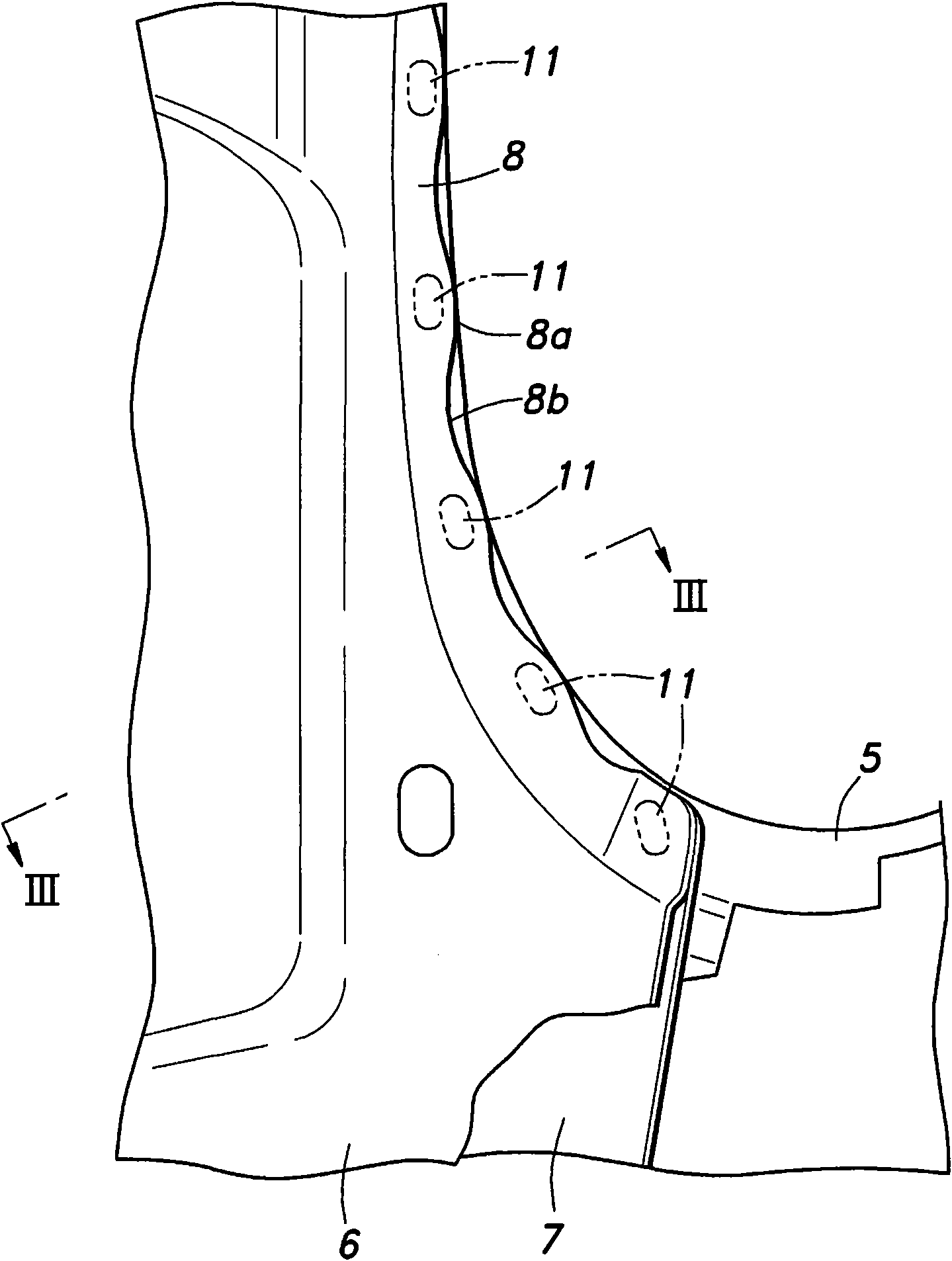
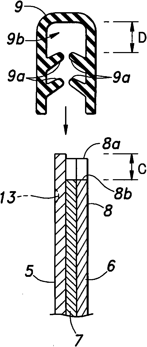
[0027] Such as figure 2 As shown, the center pillar 3 includes two workpieces, namely, a center pillar outer 5 formed as a part of the outer panel 4 and a center pillar inner 6 overlapping the center pillar outer 5 from the inside of the vehicle interior. Additionally, if image 3 As shown, between the center pillar outer member 5 and the center pillar inner member 6, a center pillar reinforcing plate 7 is provided in a sandwiched state.

[0028] The spot welding of the inner member and the outer member of the frame including the door opening of the center pillar 3 configured in this wa...


PUM


Abstract

Work pieces for a center pillar are provided with marks for determining locations for spot welding which are easy to recognize, and this simplifies the task of managing the quality of welding work. The center pillar 3 is formed by a center pillar outer 5 and a center pillar inner 6 in such a manner that a flange 8 formed in the center pillar inner is spot welded to a corresponding part of the center pillar outer. The edge of the flange is given with a wavy shape to indicate the locations for spot welding by the peaks of the wavy shape. As opposed to dents or recesses which cannot be deep enough to be readily recognizable owing to the limit in the thickness of the work piece, the wavy shape may be of such dimensions as to permit required recognizability. This ensures spot welding to be performed on designed locations, and improves the quality of the spot welding work.

Description

technical field [0001] The present invention relates to a plurality of workpieces to be spot welded to each other. Background technique [0002] Conventionally, as a frame of an automobile body, for example, a center pillar is provided between front and rear doors of a passenger car. In such a center pillar, the workpieces constituting the inner and outer sides of the vehicle body are used, and the workpieces are overlapped so as to form a space with a substantially rectangular cross-section between the two workpieces, and the parts that are in contact with each other are spot welded so that the two The workpiece is integrated and formed. Moreover, in order to perform this spot welding easily, a flange is provided on the edge part of at least one of the workpieces, and spot welding is performed on the flange (for example, refer patent document 1). [0003] Patent Document 1: Japanese Patent Application Laid-Open No. 6-278466 [0004] When spot welding the flange of the wo...

Claims


Application Information

Patent Timeline
Patent Type & Authority Applications(China)
IPC IPC(8): B23K11/11B23K11/00B62D25/04
CPCB23K2201/006B62D25/04B23K33/008B23K11/11B23K2101/006
Inventor 安片瞳藤井宽二关根恒介
Owner HONDA MOTOR CO LTD
Why Eureka
Try Eureka