Pneumatic tire

一种充气轮胎、轮胎周向的技术,应用在重型轮胎、轮胎零部件、轮胎胎面/胎面花纹等方向,能够解决轮胎低滚动阻力性等问题,达到减小滚动阻力、保持滚动阻力、提高抗偏磨耗性的效果

Inactive Publication Date: 2010-01-13
THE YOKOHAMA RUBBER CO LTD
View PDF1 Cites 6 Cited by
  • Summary
  • Abstract
  • Description
  • Claims
  • Application Information

AI Technical Summary

Problems solved by technology

However, the traction pattern tends to reduce the low rolling resistance of the tire

Method used


Image

  • Pneumatic tire
  • Pneumatic tire
  • Pneumatic tire

Examples


Embodiment approach

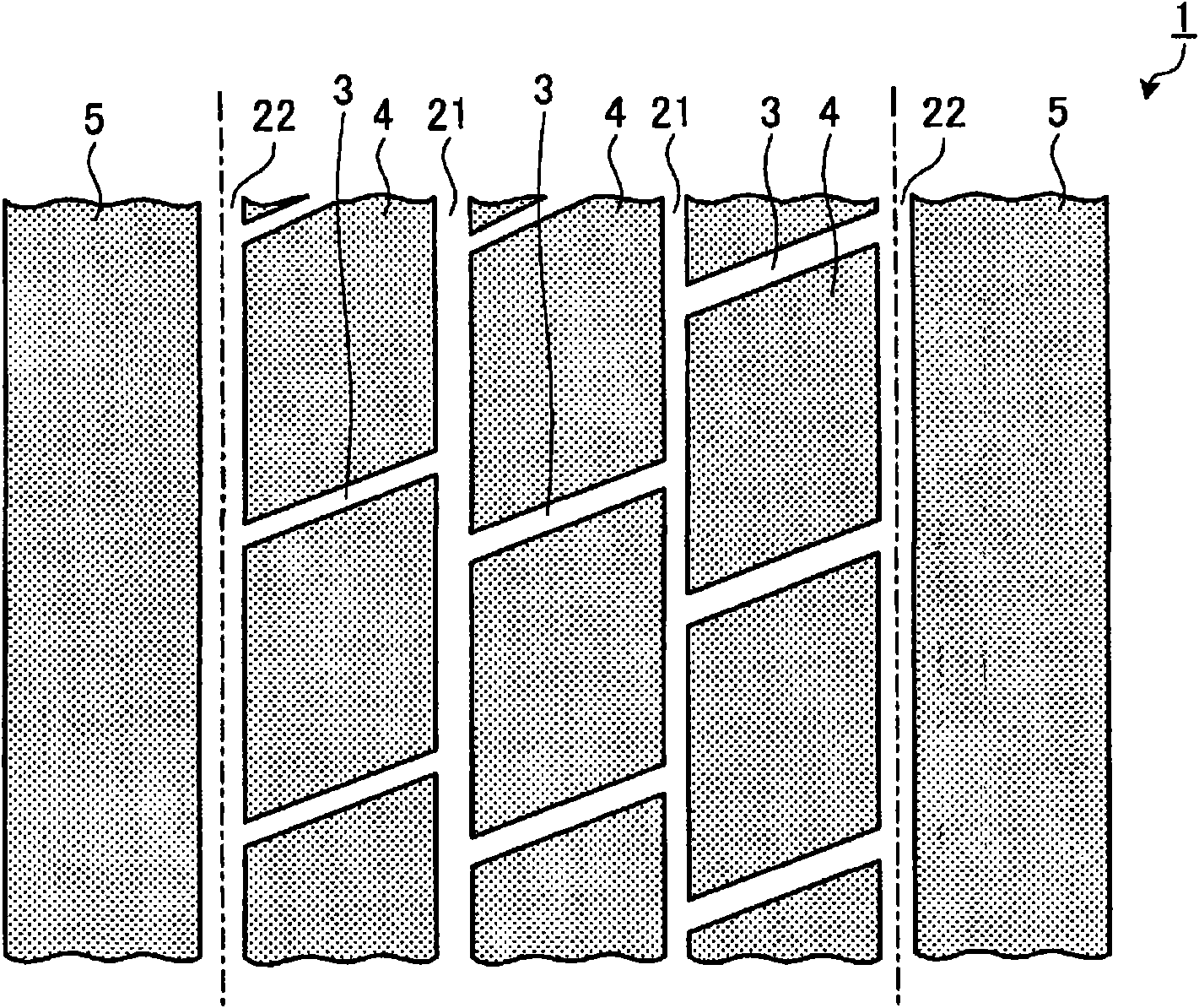
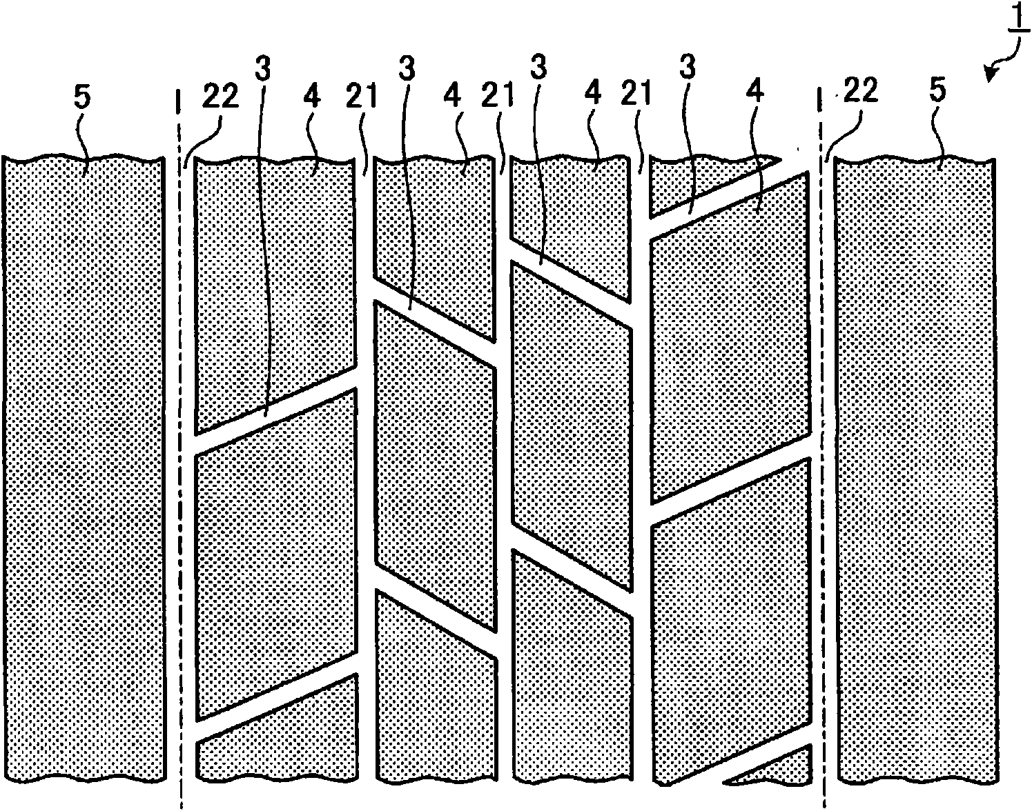
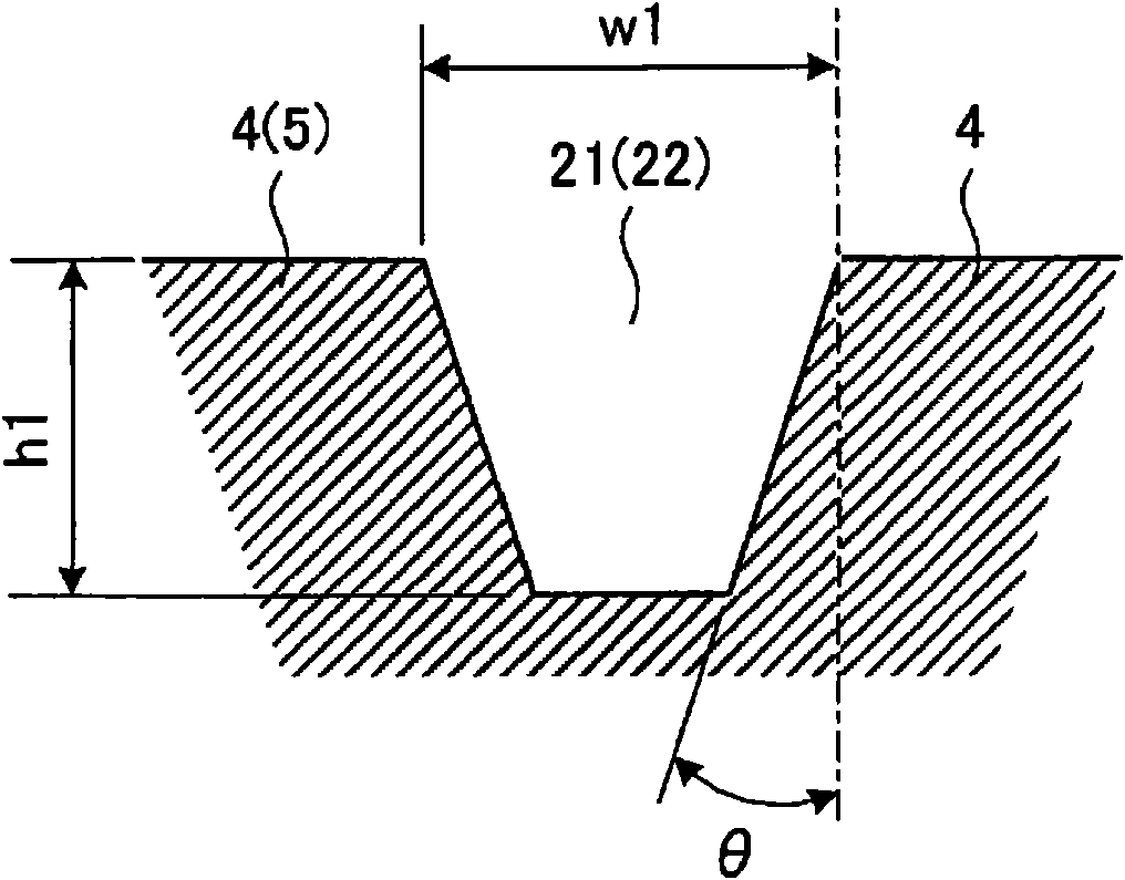
[0046] figure 1 is a top view of a tread of a pneumatic tire according to an embodiment of the present invention. Figure 2-6 yes figure 1 A schematic diagram of a modified version of the pneumatic tire shown. Figure 7 is a result table of the performance test of the pneumatic tire according to the embodiment of the present invention.

[0047]In the pneumatic tire 1, a traction pattern is formed on the tread portion, including: three or more circumferential main grooves 21, 22 extending in the tire circumferential direction; a plurality of widthwise grooves 3 extending in the tire width direction; and a plurality of rows The land portions 4 , 5 defined by the circumferential main grooves 21 , 22 and the widthwise groove 3 . The centerline I of the outermost circumferential main groove 22 in the tire width direction serves as a boundary line at which the tread portion is divided into a center region and a shoulder region. The shoulder area is the area from the center line ...


PUM


Abstract

A pneumatic tire having reduced rolling resistance with its high snow traction performance maintained. The pneumatic tire (1) has a tread center region and tread shoulder regions divided by the center lines (I) of circumferential main grooves (22) located on the outermost sides in the lateral direction of the tire. Further, the ratio G = (A + B) / X which is the ratio of the sum (A + B) of the groove area A of circumferential grooves (21, 22) and the groove area B of lateral grooves (3) to the area X of ground contact of the tread is G = 0.25, the ratio S = B / (A + B) which is the ratio of the groove area B of the lateral grooves (3) to the sum (A + B) of the groove area A of the circumferential grooves (21, 22) and the groove area B of the lateral grooves (3) is 0.25 < S < 0.45, and the ratio Gs = C / Y which is the ratio of the groove area C of the tread shoulder regions to the area Y of ground contact of the tread shoulder regions is Gs < 0.20, and the ratio G and the ratio Gs has the relationship of Gs < G.

Description

technical field [0001] The present invention relates to a pneumatic tire. More specifically, the present invention relates to a pneumatic tire whose rolling resistance can be reduced while maintaining the snow traction performance of the tire. Background technique [0002] In the pneumatic tire with the traction pattern, widthwise grooves are provided in the tread center region and the shoulder region to ensure snow traction performance. However, the traction pattern tends to lower the low rolling resistance of the tire. The purpose of the above arrangement is to improve the low rolling resistance while maintaining the snow traction performance of the tire. [0003] As a conventional pneumatic tire having the above-mentioned purpose, the technology disclosed in Patent Document 1 is known. In conventional pneumatic tires (heavy-duty radial tires), there are four longitudinal main grooves extending continuously in the circumferential direction and the groove width is not le...

Claims


Application Information

Patent Timeline
Patent Type & Authority Applications(China)
IPC IPC(8): B60C11/03B60C11/00B60C11/04B60C11/13
CPCB60C11/0306B60C2200/06B60C11/00B60C2011/0025B60C11/033B60C11/0309Y02T10/86
Inventor 中野智也
Owner THE YOKOHAMA RUBBER CO LTD
Why Eureka
Try Eureka