Fluid controller

A technology for fluid controllers and shells, which is applied to shock absorbers, devices for absorbing fluid energy in valves, shock absorbers, etc., which can solve problems affecting the opening and closing of diaphragms and pressure control actions, and improve vibration resistance Effect

Inactive Publication Date: 2010-01-13
FUJIKIN INC
View PDF1 Cites 12 Cited by
  • Summary
  • Abstract
  • Description
  • Claims
  • Application Information

AI Technical Summary

Problems solved by technology

[0004] However, in the fluid controller of the aforementioned Patent Document 1, the addition of the anti-vibration spring has the same effect as changing the style of the pressure setting spring, so there is a problem of affecting the opening and closing of the diaphragm, that is, affecting the pressure control operation.

Method used


Image

  • Fluid controller
  • Fluid controller
  • Fluid controller

Examples


Embodiment Construction

[0040] Embodiments of the present invention will be described with reference to the following drawings. In the following description, up and down and left and right refer to up and down and left and right in the drawing.

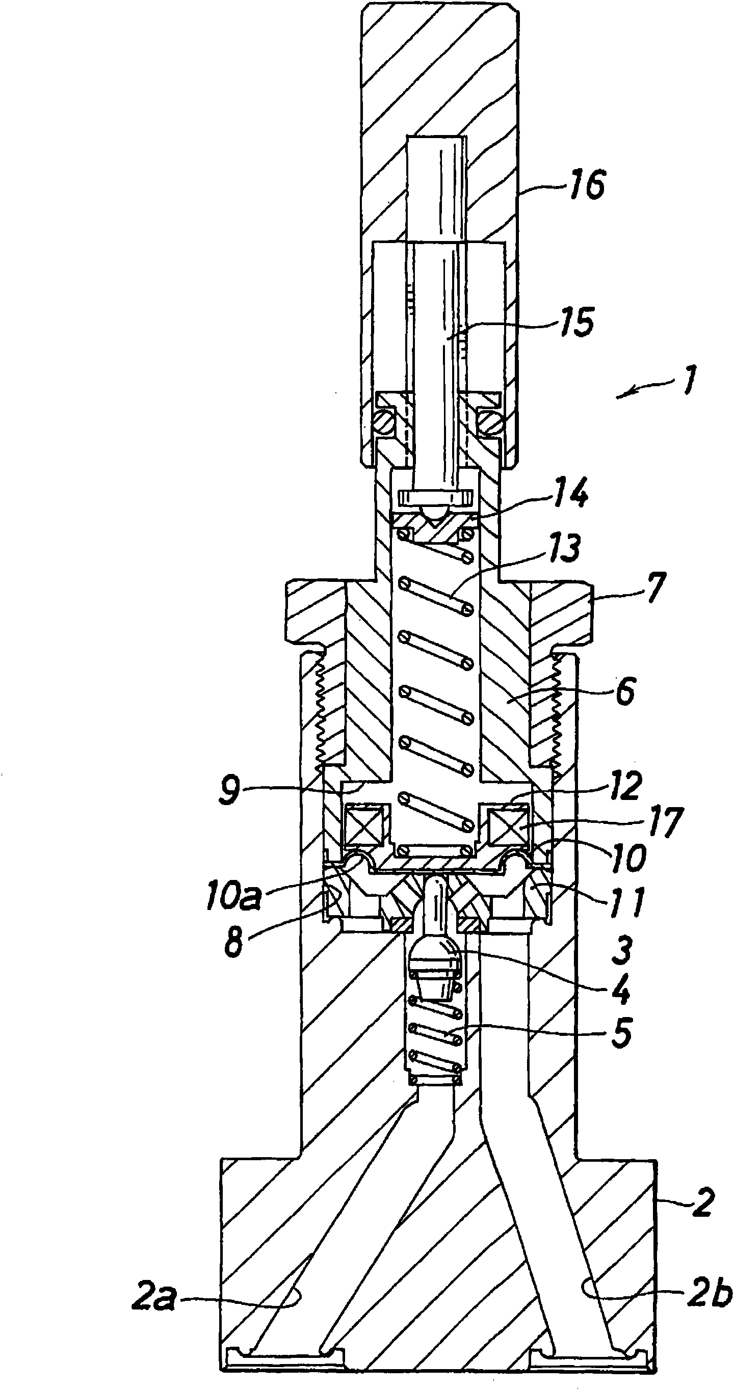
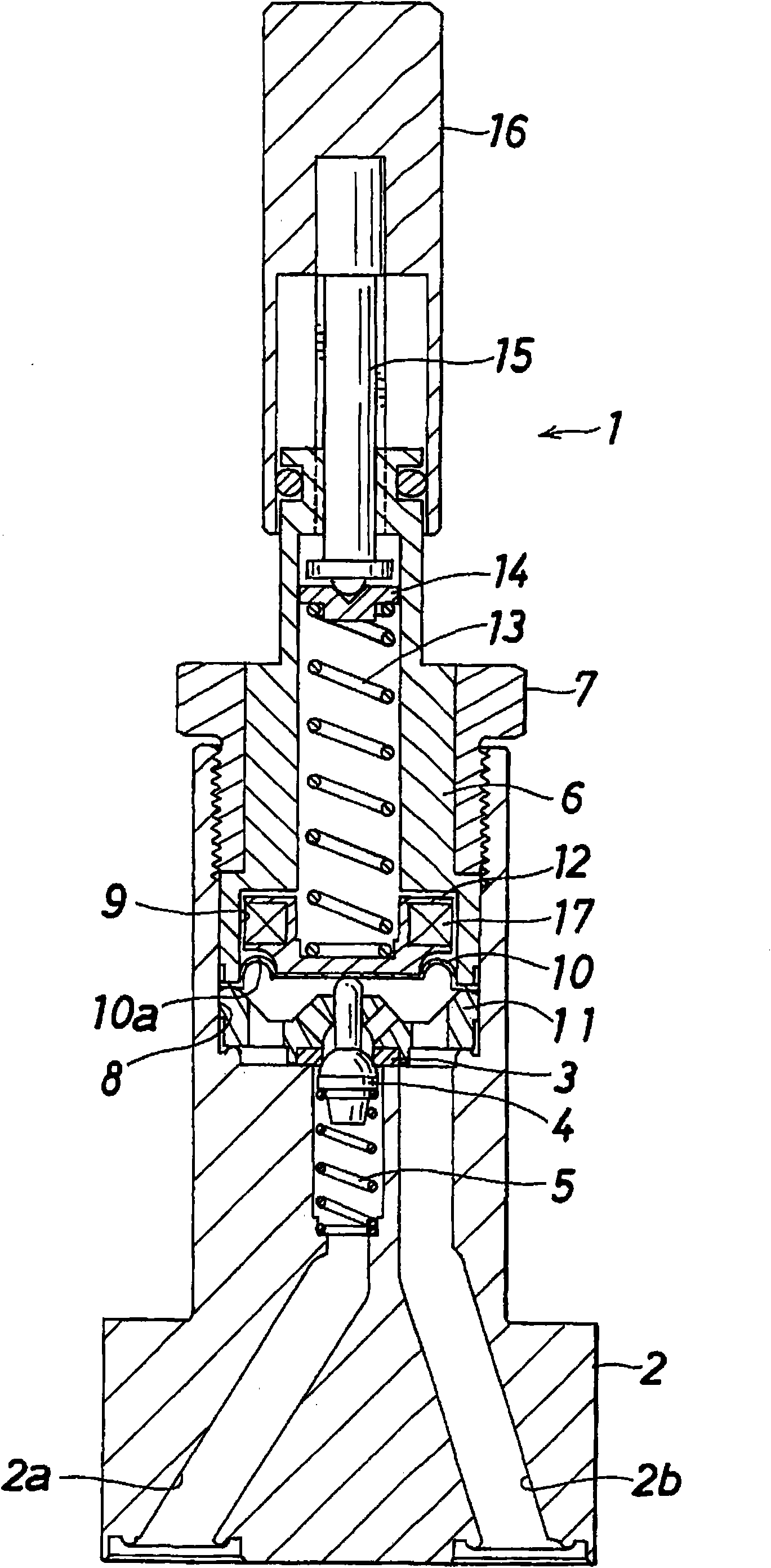
[0041] Figure 1 to Figure 4 One embodiment of the fluid controller of the present invention is shown.

[0042] Such as figure 1 with figure 2 As shown, the fluid controller 1 has: a valve box 2 having a fluid inflow passage (high pressure fluid inflow passage) 2a and a fluid outflow passage (low pressure fluid outflow passage) 2b; Shaped valve seat 3; movably disposed in the fluid inflow passage 2a, and is pushed (moved in the closing direction) or separated (moved in the opening direction) relative to the annular valve seat 3 to open and close the fluid inflow passage 2a A poppet valve (valve body) 4; configured in the fluid inflow passage 2a, the poppet spring spring 5 that springs up the poppet valve 4; the lower end is fixed on the housing 6 at the...


PUM


Abstract

Provided is a fluid controller of which the vibration-proof performance is improved without affecting its pressure control operation. A valve element (4) is moved relative to a valve seat (3) due to a change in balance between the fluid pressure applied to a diaphragm (10) and the elastic force by a pressure setting spring (13), whereby the fluid pressure is controlled. A vibration-proof member (17) is disposed on a disk-like movable member (12) moving integrally with the diaphragm (10). The vibration-proof member (17) has a weight interposed between elastic bodies built in a casing.

Description

technical field [0001] The present invention relates to a fluid controller called a pressure reducing valve, and more particularly to a fluid controller with improved vibration resistance. Background technique [0002] As a vibration suppressing mechanism for a fluid controller, Patent Document 1 discloses a fluid controller. A valve seat and a valve body are provided on the valve chamber side of a diaphragm that divides the interior of the fluid controller into a valve chamber and an adjustment chamber. A pressure setting spring is installed on the side of the adjustment chamber, and an anti-vibration spring that can change the overall spring constant and weight is interposed between the diaphragm and the pressure setting spring. [0003] Patent Document 1: Japanese Patent Publication No. 4-13586 ( figure 1 ) [0004] However, in the fluid controller of Patent Document 1, the increase of the anti-vibration spring has the same effect as changing the style of the pressure s...

Claims


Application Information

Patent Timeline
IPC IPC(8): F16K17/04F16K17/30F16K47/02
CPCF16K17/0453F16K17/085F16F7/116F16F9/341F16F7/112Y10T137/7821Y10T137/7793F16K31/1262F16K7/12
Inventor 小艾睦典
Owner FUJIKIN INC
Why Eureka
Try Eureka