Electrochemical single cells for a battery and battery

An electrochemical, single-unit technology, applied in electrochemical generators, secondary batteries, battery cooling/heating, etc., can solve cost-intensive and other problems

Inactive Publication Date: 2010-01-13
DAIMLER AG
View PDF2 Cites 19 Cited by
  • Summary
  • Abstract
  • Description
  • Claims
  • Application Information

AI Technical Summary

Problems solved by technology

So the known design is

Method used


Image

  • Electrochemical single cells for a battery and battery
  • Electrochemical single cells for a battery and battery
  • Electrochemical single cells for a battery and battery

Examples


Embodiment Construction

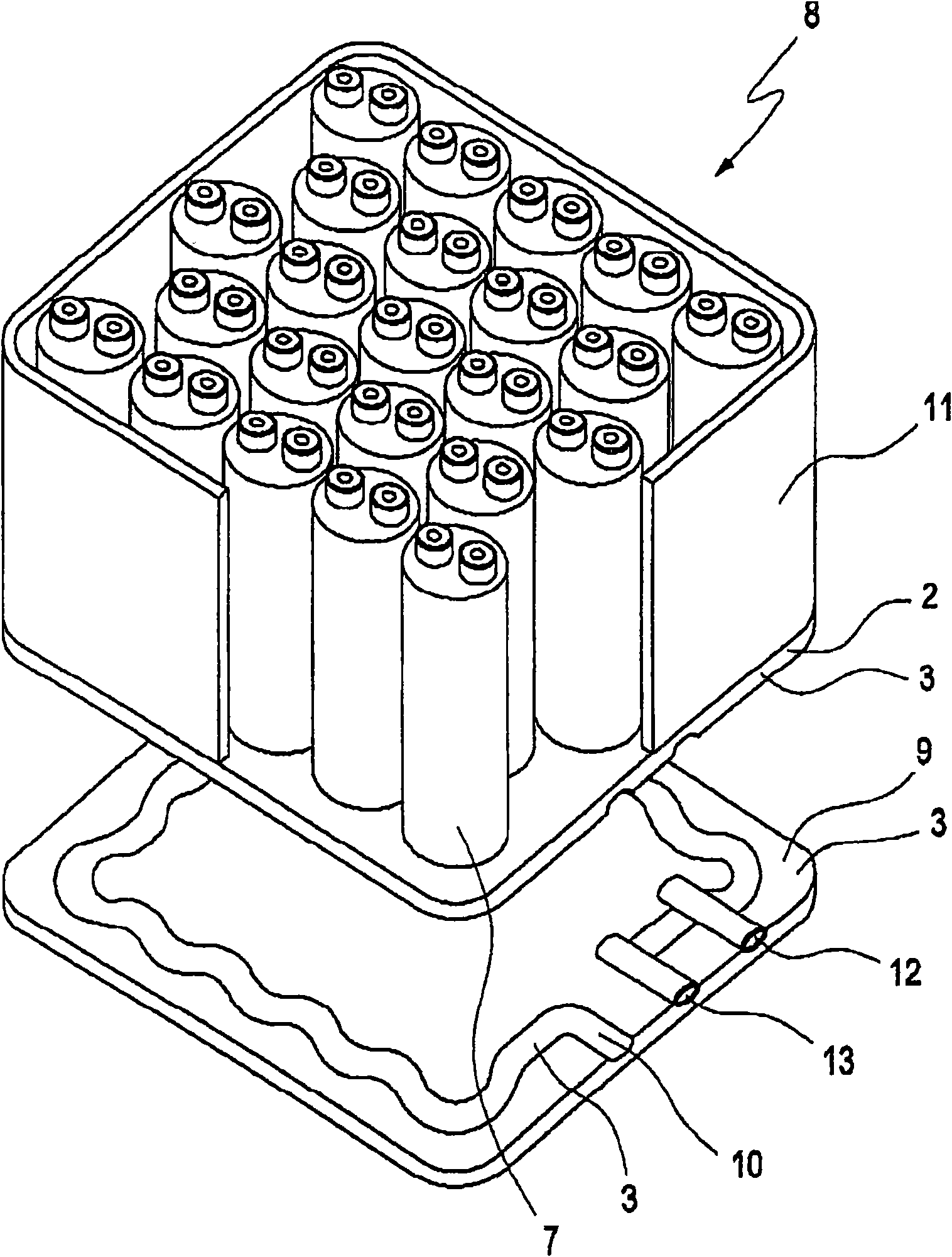
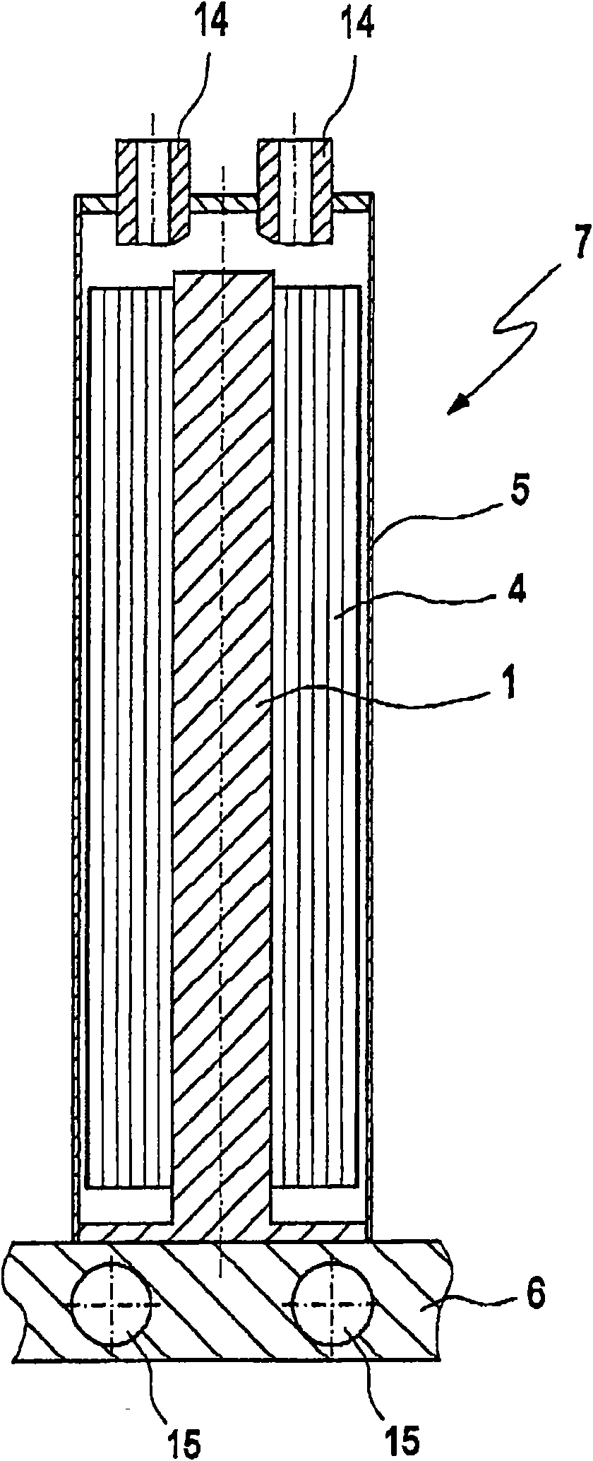
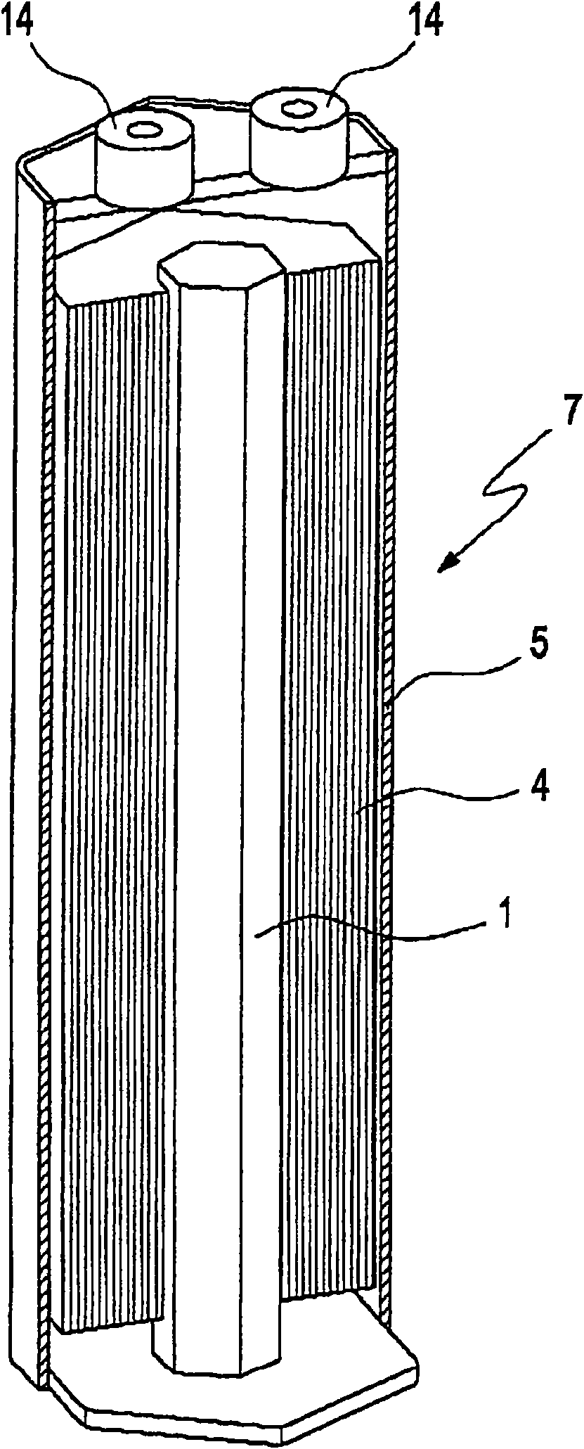
[0021] exist figure 1 A battery 8 is shown in , which also includes a plurality of cells 7 electrically connected to each other. The cells 7 are arranged in an in particular completely closed battery housing 11 . The single body 7 is arranged on a heat conducting unit 2 designed as a metal plate. The cells 7 are arranged on the heat conduction unit 2 with their longitudinal axes parallel to each other, wherein the heat conduction rod 1 of each cell 7 is thermally connected to the heat conduction unit 2 .

[0022] Together with the base plate 9 and the cooling coil 10 arranged between these two plates 2 , 9 , the heat conducting unit 2 forms a temperature control unit 3 for at least a part of the cells 7 of the battery 8 . With the temperature control unit 3 it is possible in a simple and cost-effective manner to advantageously influence the temperature in the cell 7 connected thermally to it.

[0023] Furthermore, in a suitable manner, the cooling coil 10 can additionally b...


PUM


Abstract

An electrochemical single cell for a battery and battery made from said single cells. The single cell comprises an electrode stack wound about a heat conducting bar and/or folded around a heat conducting bar. Temperature control of the single cells can be achieved by means of the heat conducting bar being at least partly made from a highly thermally conductive material on the surface thereof facing the electrode stack and having a solid construction. An economical and simple temperature management of a battery can be guaranteed, wherein the battery has a thermally conducting bar in thermal connection with a temperature control unit.

Description

technical field [0001] The invention relates to an electrochemical cell for a battery / accumulator according to the preamble of claim 1 and to a battery consisting of such a cell according to the preamble of claim 9 , Both are known, for example, from DE 103 58 582 A1 as the basis for the correlation. Background technique [0002] An electrochemical cell for batteries is disclosed in DE 103 58 582 A1, which is used in particular for the production of high-performance / high-efficiency batteries. Batteries of this type are preferably used to at least partially drive passenger motor vehicles, such as passenger cars or coaches. Preferred battery systems are in particular lithium-ion batteries and / or nickel-metal hydride batteries, in which a plurality of cells are connected to one another in parallel or in series. In known monoliths, a multi-layer stack / group of pole pieces made of a diaphragm - two pole piece films with a diaphragm in between, preferably aluminium / diaphragm / cop...

Claims


Application Information

Patent Timeline
IPC IPC(8): H01M10/50H01M6/50B60R16/04
CPCY02E60/12H01M10/5042H01M10/5004H01M10/5057H01M6/5038H01M10/5016H01M10/5095H01M10/5077H01M10/503H01M10/5053H01M10/625H01M10/663H01M10/654H01M10/6556H01M10/6568H01M10/643H01M10/6554H01M10/613Y02E60/10Y02P70/50
Inventor J·迈因特施尔D·施勒特尔
Owner DAIMLER AG
Why Eureka
Try Eureka