
Bar brush machine

A strip brush machine and body technology, applied in the direction of brushes, bristles, household appliances, etc., can solve the problems of frequent replacement, short service life of blades, unreasonable blade structure design, etc., and achieve reasonable blade configuration, reasonable structure design, reduce The effect of cutting power

Inactive Publication Date: 2010-01-20
桐乡市永鑫制刷机械厂
View PDF0 Cites 4 Cited by
  • Summary
  • Abstract
  • Description
  • Claims
  • Application Information

AI Technical Summary

Problems solved by technology

[0002] At present, the strip brush machine is more and more widely used in the field of industrial production, but the strip brush machine of the prior art has the defects of the following structure and working method: first, the hair feeding device is usually a swing type, and a hair removal rod is used to remove the hair from the hair storage device. The box moves back and forth to complete the process of wool picking and wool feeding. This kind of working method has less hair feeding per unit time and low work efficiency, which often becomes the bottleneck affecting the efficiency of the strip brush machine. In addition, frequent swings are not conducive to the stability of hair feeding. At the same time, it is easy to cause damage to the equipment and cause equipment failure; secondly, the shearing force of the existing shearing device is not enough, the operation is unstable, resulting in incomplete shearing, and the remaining material of the bristles sticks to the strip brush
At the same time, due to the unreasonable design of the blade structure, the blade has a short service life and needs to be replaced frequently, resulting in uneven and uneven incision heights of the brush, which directly affects the decline of the quality of the brush; moreover, the shearing force of the existing shearing device Insufficient, unstable operation, resulting in incomplete shearing, deformation of the incision profile, uneven incision with many burrs, and adhesion between profiles
At the same time, due to the unreasonable design of the blade structure, the blade has a short service life and needs to be replaced frequently, which directly affects the quality of the brush.

Method used

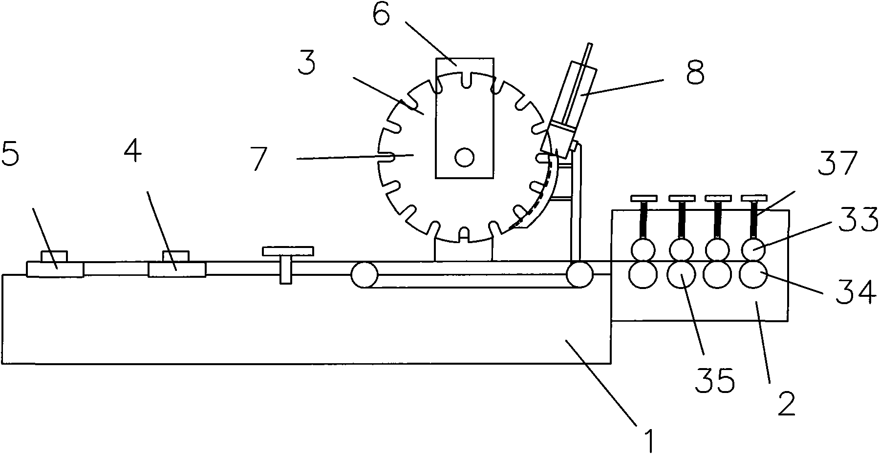

Image

  • Bar brush machine
  • Bar brush machine
  • Bar brush machine

Examples


Embodiment 1

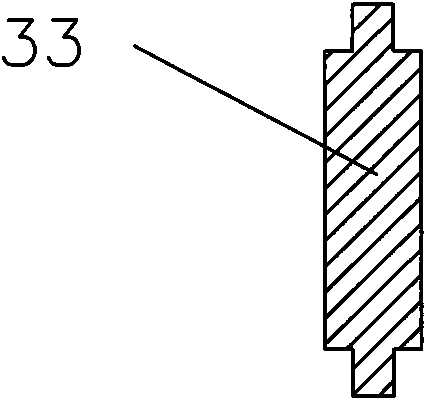
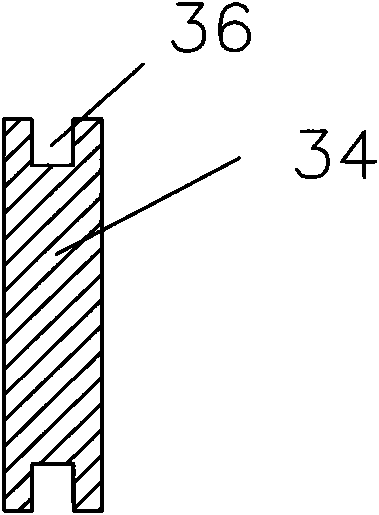
[0022] Such as figure 1 As shown, the strip brush machine described in this embodiment includes a body 1, a strip forming device 2, a hair feeding device 3, a shearing device 4 and a shearing device 5, a strip forming device 2, a hair feeding device 3, a shearing device 4 and a shearing device 5. The device 5 is arranged on the body 1 in turn, the hair feeding device 3 includes a frame 6, the frame 6 is provided with a circular hair feeding tray 7, and a hair storage device used in conjunction with the hair feeding tray 7 is provided beside the hair feeding tray 7 8. The slitting device 2 is formed by parallel arrangement of four groups of upper pressure rollers 33 and lower molding wheels 34 with a wheel-type slitting structure 35 arranged in parallel, as figure 2 As shown, the edge section of the upper pressure roller 33 can be in a "convex" shape, such as image 3 As shown, the edge of the lower mold wheel is provided with a groove 36 cooperating with the upper pressure r...

Embodiment 2

[0024] Such as Figure 4 As shown, the strip brush machine described in this embodiment, on the basis of Embodiment 1, the hair-feeding disc 7 mainly includes a disc body 9, and the edges of the disc body 9 are provided with fur-feeding grooves 10 at intervals. The top can be inclined, and a groove wall of the wool groove 10 forms a tip 11 with the edge of the disc body 9, and the other groove wall forms an arc 12 with the edge of the disc body 9, such as Figure 5 As shown, the disc body 9 becomes thinner from the center of the disc body 9 to the edge of the disc body 9, the center of the disc body 9 may be provided with a shaft hole 13, and the shaft hole 13 is provided with a shaft connection structure 14, and the shaft connection structure 14 is arranged in the shaft hole The keyway on 13, hair storage device 8 comprises hair box 15, is provided with depression bar 16 in the hair box 15, and hair box 15 is inclined setting, is provided with arc-shaped hair guide groove 17 ...

Embodiment 3

[0026] Such as image 3 As shown, in the strip brush machine described in this embodiment, on the basis of Embodiment 2, the shearing device 4 mainly includes a shearing knife 22, and the shearing knife 22 can be composed of two blades that are cut in planes on the left and right, one of which is a fixed blade 23, and the other One piece is a movable blade 24; the movable blade 24 is arranged in the blade moving channel 25, and the end of the movable blade 24 can be connected with a blade pushing arm 26, and the blade pushing arm 26 is hingedly connected with a connecting rod 27, and the connecting rod 27 is hingedly connected to the eccentric wheel 28, the eccentric wheel 28 is fixedly connected with the drive shaft 29, the drive shaft 29 is arranged on the drive wheel 30, the drive wheel 30 and the power wheel 32 are connected in transmission, and the power wheel 32 is connected to the motor. Shearing device 5 can mainly comprise cutter 31 and cylinder 47, and cutter 31 can ...


PUM


Abstract

The invention discloses a bar brush machine which comprises a machine body, and a bar forming device, a hair feed device, a hair shearing device and a cutting-off device which are sequentially arranged on the machine body, wherein the hair feed device comprises a stand provided with a circular hair feed disc, and a hair storage device matched with the hair feed disc is arranged beside the hair feed disc. The hair feed disc uniformly delivers hair in the hair storage device to the bar brush machine by rotating, realizing uniform delivery; and the delivery is more stable. The invention solves the problem of unstable delivery of previous swinging type hair feed devices, and obviously reduces failure rate. On the other hand, the delivery speed is quicker, the efficiency is higher and the structures of the hair shearing device and the cutting-off device are reasonably designed, so that the bar brush machine can run stably for a long time. In addition, a reasonably configured blade has long service life and reduces shearing and cutting power consumption, so that bar brushes with high quality can be produced.

Description

technical field [0001] The invention relates to a strip brush machine. Background technique [0002] At present, the strip brush machine is more and more widely used in the field of industrial production, but the strip brush machine of the prior art has the defects of the following structure and working method: first, the hair feeding device is usually a swing type, and a hair removal rod is used to remove the hair from the hair storage device. The box moves back and forth to complete the process of wool picking and wool feeding. This kind of working method has less hair feeding per unit time and low work efficiency, which often becomes the bottleneck affecting the efficiency of the strip brush machine. In addition, frequent swings are not conducive to the stability of hair feeding. It is also easy to cause damage to the equipment and cause equipment failure; secondly, the shearing force of the existing shearing device is not enough, and the operation is unstable, resulting ...

Claims


Application Information

Patent Timeline
IPC IPC(8): A46D1/06
Inventor 沈建彬
Owner 桐乡市永鑫制刷机械厂
Learn More