Linear unit

A linear unit and component technology, applied in the direction of linear motion bearings, bearings, fluid pressure actuators, etc., can solve the problems of increasing the pressure per unit area and reducing the bearing surface

Inactive Publication Date: 2010-01-20
FESTO AG & CO KG
View PDF1 Cites 13 Cited by
  • Summary
  • Abstract
  • Description
  • Claims
  • Application Information

AI Technical Summary

Problems solved by technology

However, this will reduce the bearing surface, a...

Method used


Image

  • Linear unit
  • Linear unit
  • Linear unit

Examples


Embodiment Construction

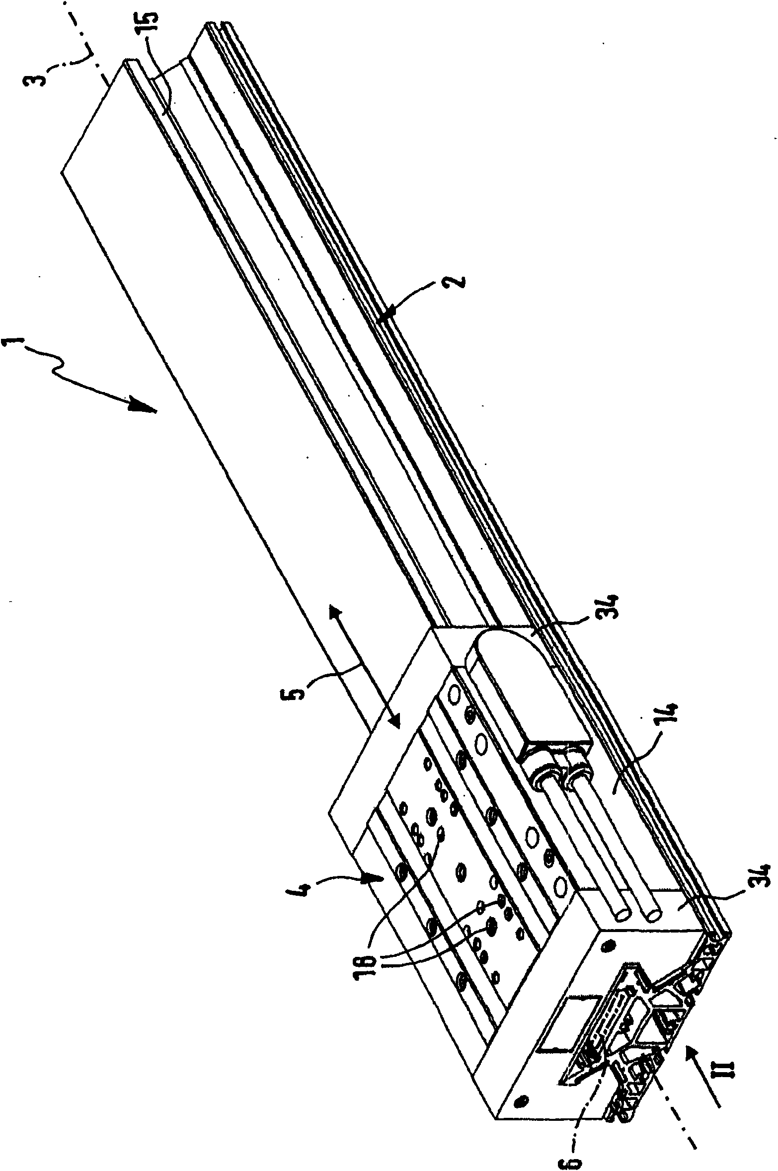
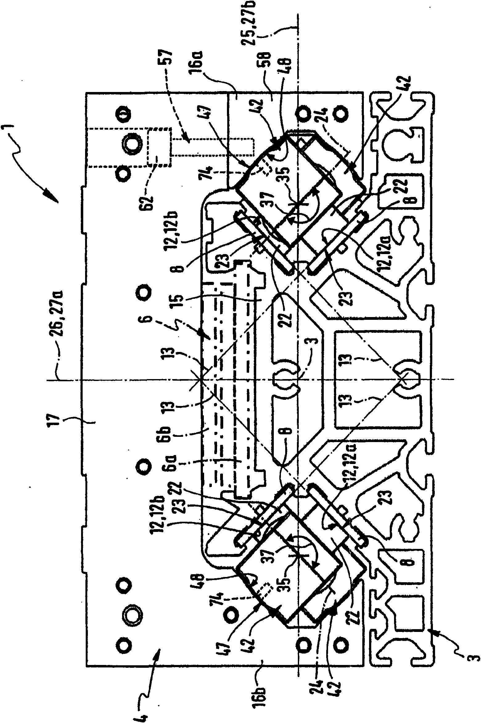
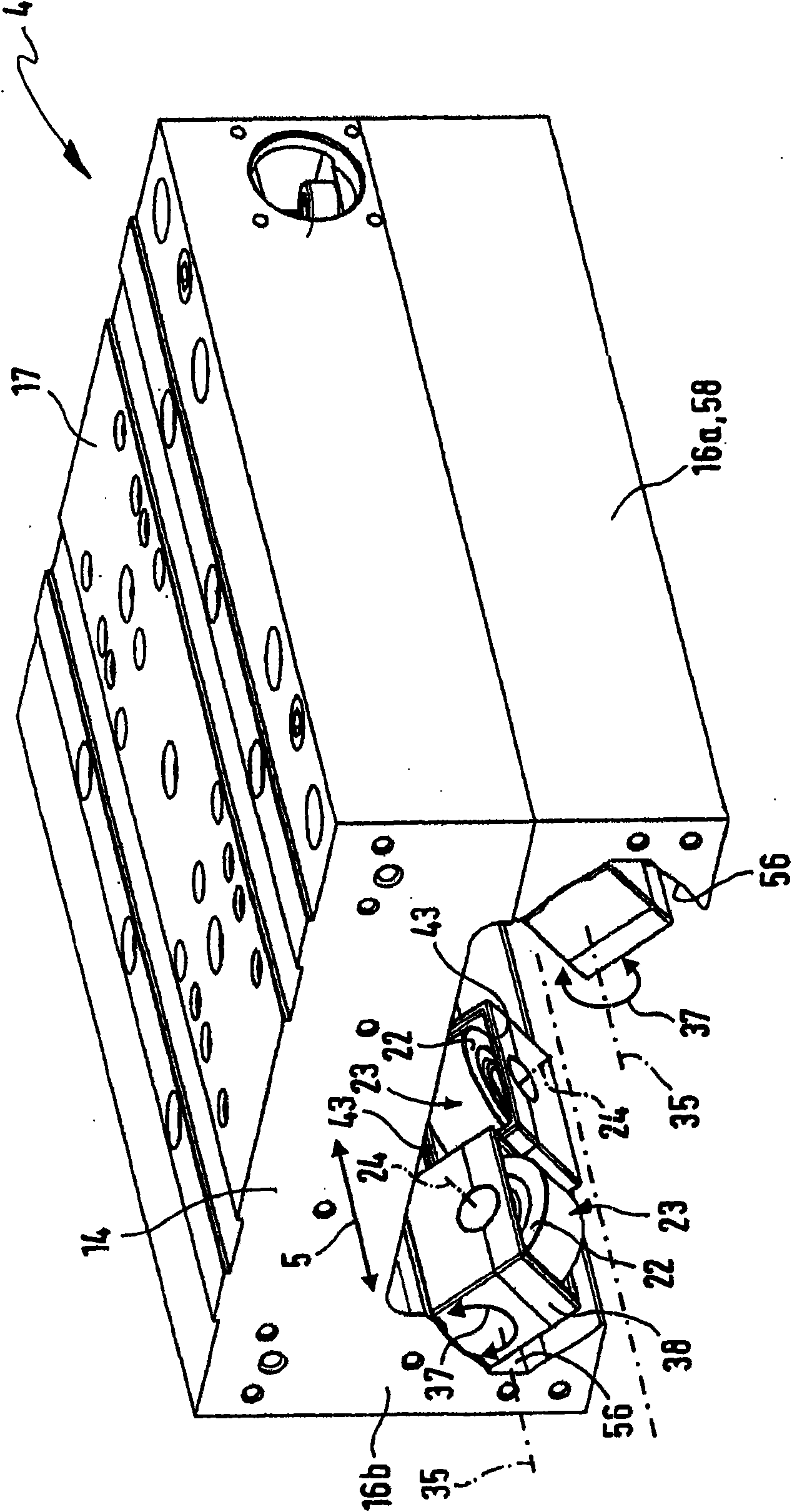
[0035]The linear unit indicated as a whole by the reference number 1 comprises a base element 2 with a longitudinal extension, the longitudinal axis of which is indicated by a dotted line representing the main axis 3, on which the slide 4 is mounted in such a way that It is capable of performing a reciprocating linear movement 5 indicated by a double arrow relative to the base element 2 in the axial direction of the main axis 3 .

[0036] It is expedient to design the linear unit 1 in the form of a linear drive with only a drive member 6 shown in dotted lines in the figure, which acts between the base element 2 and the slide 4 in order to generate the drive force causing the linear movement 5 . By way of example, it may be an electric drive member 6 , in particular of the type forming an electric linear direct drive system. A first drive unit 6 a indicated by dashed lines is fixedly mounted on the base element 2 , and a second drive element 6 b cooperating with it in a non-co...


PUM


Abstract

The linear unit (1) has a base element, at which a carriage (4) is mounted in a linear movable manner in axial direction of a main axis (3). The base element has multiple longitudinal guide paths (12,12a,12b) extended to the main axis. A supporting roller (22) is fixed with a carriage body (14) of a carriage. The supporting roller is movement-coupled with circumferential-sided circular-cylindrical bearing surface (23) such that supporting roller is unrolled during the linear movement of the carriage on the assigned guide paths.

Description

technical field [0001] The invention relates to a linear unit, comprising a base element on which a slide block capable of linearly moving in the axial direction of the main axis is installed; the base element has a plurality of flat guide rails extending along the main axis, at least one The cylindrical rolling surface on the circumferential side of the support roller coupled with the motion of the slider body is attached to the flat guide rail. When the slider moves linearly, the support roller will roll on the corresponding guide rail and rotate around the axis perpendicular to the main axis. axis of rotation rotates. Background technique [0002] DE 19514846 A1 discloses such a linear unit, the slider of which is movably supported in the direction of the main axis on an elongated base element via support rollers supported by the slider body. When the slider moves in a straight line, the cylindrical rolling surface of the support roller will roll on the flat guide rail o...

Claims


Application Information

Patent Timeline
IPC IPC(8): F16C29/04F15B15/20
CPCF16C29/045F16C29/001
Inventor T·费勒
Owner FESTO AG & CO KG
Why Eureka
Try Eureka