Pneumatic tire
A technology for pneumatic tires and treads, which is applied to tire parts, tire treads/tread patterns, vehicle parts, etc. It can solve the problems of developing cracks, easy cracks at the bottom of grooves, cracks in protective grooves, etc., and achieves improved Effects of resistance to stone trapping, improvement of protection ditch crack resistance and groove bottom crack resistance
Active Publication Date: 2010-01-20
BRIDGESTONE CORP
View PDF2 Cites 15 Cited by
- Summary
- Abstract
- Description
- Claims
- Application Information
AI Technical Summary
Problems solved by technology
[0009] Additionally, if Figure 8 As shown, when a large load Fa is applied to the tread center side portion 103 of the shoulder rib when the pneumatic tire runs over, for example, a curb, etc., there is an angle of the tire radially outer side portion from the depth of the annular groove 101. Part 104 starts to have problems such as cracks 105
[0010] Additionally, if Figure 9 As shown, when the pneumatic tire is used for a long period of time, the annular groove 101 is repeatedly deformed, and there is a problem that the corner 106 of the inner part in the tire radial direction deep in the annular groove 101 is wrinkled, and the wrinkle develops into a crack 107. , which has the problem that the bottom of the groove is prone to cracks
[0011] Additionally, if Figure 10 As shown, when a lateral load acts on the pneumatic tire and a large load Fb is applied to the tread end portion 102, cracks may occur from the corner portion 109 connected to the groove wall on the tread end side of the annular groove 101. 110 questions that have Figure 8 The problem shown and has the problem that it is easy to cause cracks in the protective groove
Method used
View moreImage
Smart ImageViewing Examples
Examples
Embodiment
[0079] The present invention will be described with reference to examples of high-performance tires suitable for trucks and buses.
[0080] Among tires having a tire size of 295 / 75R225 and a rim width of 8.25 inches, tires in Table 1 below were manufactured.
[0081] Table 1
[0082]
Login to View More PUM
 Abstract
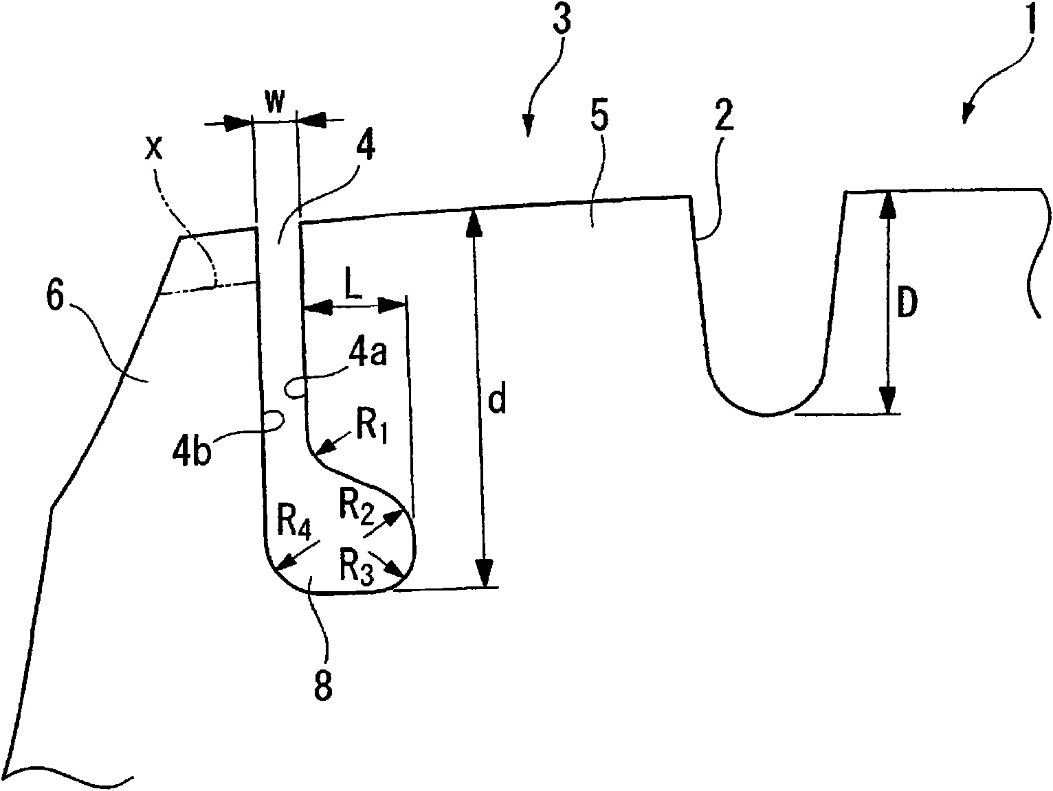
A shoulder rib (3) is provided with a thin groove (4) continuously extending in the circumferential direction of the tread of a pneumatic tire. A circumferentially continuous annular groove (8), contiguous to the bottom of the thin groove (4), is provided in a groove wall (4a) that is on the equatorial surface side of the tread in a cross-section in the lateral direction of the tread.The shape of the annular groove in a cross-section taken in the lateral direction of the tread is formed such that a corner contiguous to a groove wall on the equatorial surface side of the tread is rounded to a curvature radius R1, a corner at a portion on the outer side, in the radial direction of the tire, of a deep end portion of the annular groove is rounded to a curvature radius R2, a corner at a portion on the inner side, in the radial direction of the tire, of the deep end portion of the annular groove is rounded to a curvature radius R3, and a corner contiguous to a groove wall (4b) on the tread end side is rounded to a curvature radius R4. Stone trapping resistance, tear resistance of defense grooves, and groove bottom crack resistance are increased.
Description
technical field [0001] The present invention relates to a pneumatic tire suitable for use by trucks, buses, etc., by providing thin grooves extending continuously in the circumferential direction on the shoulder ribs divided by circumferential main grooves to prevent the occurrence of tires starting to appear on the outside of the shoulder ribs. Uneven wear development at the end edge spreads over the entire shoulder rib. Background technique [0002] In the past, thin grooves called protection grooves, which are continuous along the tread circumferential direction in a straight line, are usually provided on the shoulder ribs, and the thin grooves are used to prevent uneven wear from spreading to the entire shoulder rib or spread to the tire. The stripe pattern on the face center side. [0003] In addition to thin grooves having this function, it is also known to provide annular grooves continuous in the circumferential direction on the groove wall on the equator side of th...
Claims
Login to View More Application Information
Patent Timeline
 Patent Type & Authority Applications(China)
IPC IPC(8): B60C11/01B60C11/04B60C11/13
CPCB60C11/01B60C11/0323B60C2011/0348B60C11/1323B60C2011/013
Inventor 安藤修司
Owner BRIDGESTONE CORP
Features
- R&D
- Intellectual Property
- Life Sciences
- Materials
- Tech Scout
- Unparalleled Data Quality
- Higher Quality Content
- 60% Fewer Hallucinations
Learn More Browse by: Latest US Patents, China's latest patents, Technical Efficacy Thesaurus, Application Domain, Technology Topic, Popular Technical Reports.
© 2025 PatSnap. All rights reserved.Legal|Privacy policy|Modern Slavery Act Transparency Statement|Sitemap|About US| Contact US: help@patsnap.com


