Synchronous automatic thread release mechanism for injection mold threads

A synchronous automatic injection mold technology, applied in the field of injection mold manufacturing, can solve the problems of high labor intensity, affecting the thread removal effect, thread flanging, etc., and achieve the effects of controlling the withdrawal margin, improving the thread removal effect, and increasing the stroke space

Active Publication Date: 2011-08-31
佛山市东丽塑胶有限公司
View PDF0 Cites 0 Cited by
  • Summary
  • Abstract
  • Description
  • Claims
  • Application Information

AI Technical Summary

Problems solved by technology

[0003] One is the manual unthreading method, that is, after the mold is opened, the product is unscrewed from the mold or the movable insert by hand. The disadvantage is that the labor intensity is high and the production efficiency is low;
[0004] The second is the forced release method, that is, the injection molded part is forcibly released by the axial force of the thimble and the top plate. The production efficiency is high, but it is easy to cause radial deformation of the thread and thread flanging;
[0005] The third is the automatic thread removal method, that is, the gear is driven by an electric motor or a hydraulic motor to automatically remove the thread. The disadvantage is that the control of the thread core in the upper and lower synchronous thread strokes is not easy to operate, especially the difficulty of controlling the number of revolutions of the core core. Large, that is, it is impossible to accurately control the thread removal allowance of the core, thus affecting the thread removal effect

Method used


Image

  • Synchronous automatic thread release mechanism for injection mold threads
  • Synchronous automatic thread release mechanism for injection mold threads
  • Synchronous automatic thread release mechanism for injection mold threads

Examples


Embodiment Construction

[0015] The basic idea of ​​the present invention is to provide a clutch, which is combined with the driving gear under the action of the axial force component, so as to control the thread escape margin of the core.

[0016] The present invention will be further described below with reference to the drawings and embodiments.

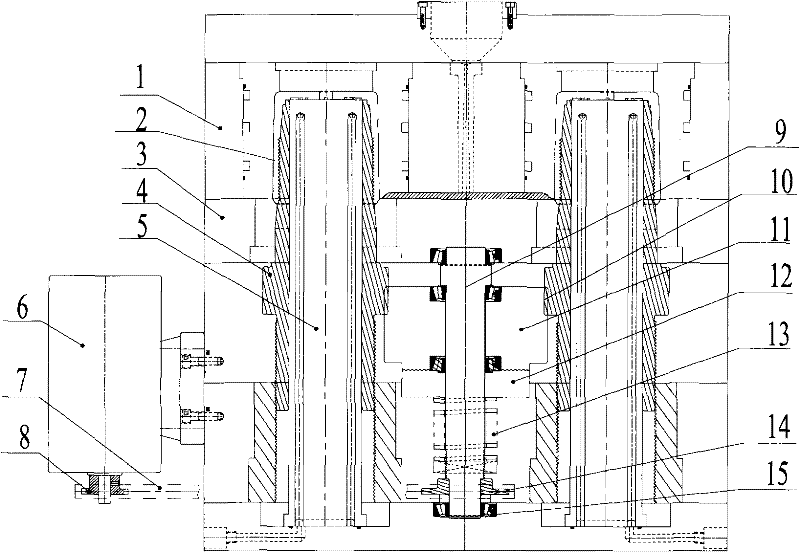
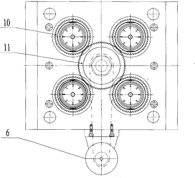
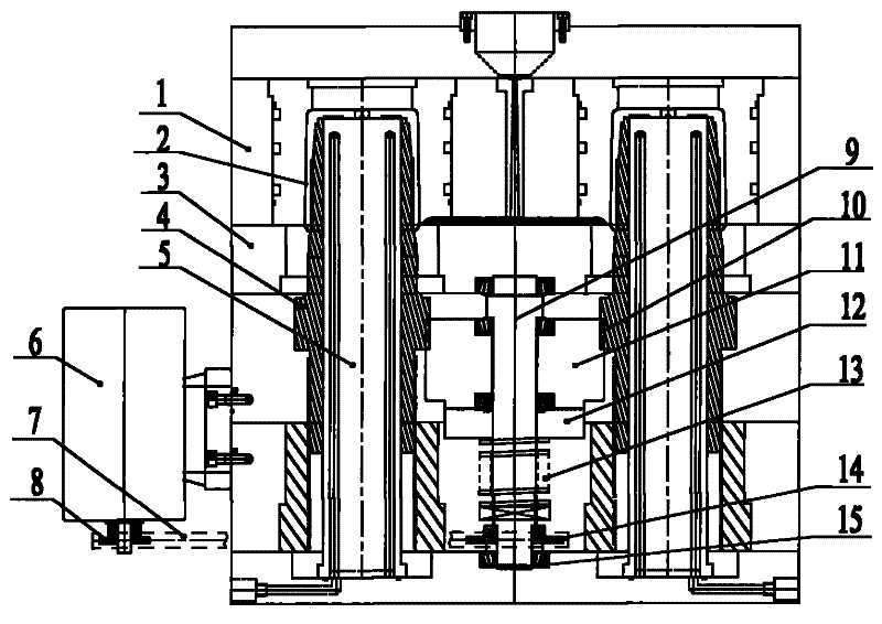
[0017] See also figure 1 , figure 2 , The injection mold includes: an upper mold 1 and a lower mold 3 to form the outer contour of the plastic part 2; several cores with threads to form the internal thread of the plastic part 2.

[0018] In order to smoothly realize the demolding of the plastic part 2, the injection mold thread synchronous automatic threading mechanism of the present invention mainly includes the following components:

[0019] A driving gear 11 is installed on a central shaft 9, which is connected to the power mechanism and the transmission mechanism to make the central shaft 9 rotate. The central shaft 9 is mounted on the injection mold through...


PUM


Abstract

The invention discloses a synchronous automatic thread release mechanism for injection mold threads, which comprises a driving gear arranged on a center shaft which is connected with a power mechanism and a driving mechanism; a plurality of driven gears respectively arranged on a core with threads; a spring sleeved on the center shaft to applying an axial force to the driving gear during operation; also comprises a clutch assembly arranged on the center shaft and positioned between the driving gear and the spring, wherein matching clutch teeth with annular distribution, obliqueness of 45+ / -0.5 degrees and heat treated surfaces are respectively arranged on a combination surface of the clutch assembly and the driving gear. By using the clutch assembly, the core is easy to control in upward and downward travels, thereby being beneficial to accurately controlling the thread release allowance of the core, and then obtaining the good thread release effect.

Description

Technical field [0001] The invention relates to the technical field of injection mold manufacturing, in particular to an injection mold thread synchronous automatic threading mechanism. Background technique [0002] At present, the commonly used methods of unthreading for injection molding of threaded plastic products (such as bottle caps) are as follows: [0003] One is the manual threading method, that is, after the mold is opened, the product is manually unscrewed from the mold or movable insert. The disadvantage is that the labor intensity is high and the production efficiency is low; [0004] The second is the forced release method, that is, the injection molded part is forced out by the axial force of the ejector pin and the top plate, and its production efficiency is high, but it is easy to cause radial deformation of the thread and thread flanging; [0005] The third is the automatic thread unthreading method, that is, the motor or hydraulic motor drives the gear to automatica...

Claims


Application Information

Patent Timeline
Patent Type & Authority Patents(China)
IPC IPC(8): B29C45/26B29L1/00
Inventor 章志明
Owner 佛山市东丽塑胶有限公司
Why Eureka
Try Eureka