Method and device for detecting interference signal

A detection method and interference signal technology, applied in the detection field, can solve problems such as inconvenient popularization, high cost, and inability to know interference signals

Inactive Publication Date: 2010-01-27
新奇点智能科技集团有限公司
View PDF0 Cites 7 Cited by
  • Summary
  • Abstract
  • Description
  • Claims
  • Application Information

AI Technical Summary

Problems solved by technology

[0008] However, the above two detection methods will have certain problems when they are used for actual ACI signal detection. For example, in detection method 1), RFRSSI and baseband RSSI need to be used to detect interference signals, and the hardware implementation is relatively complicated, and cannot To know what kind of interfere

Method used


Image

  • Method and device for detecting interference signal
  • Method and device for detecting interference signal
  • Method and device for detecting interference signal

Examples


Embodiment Construction

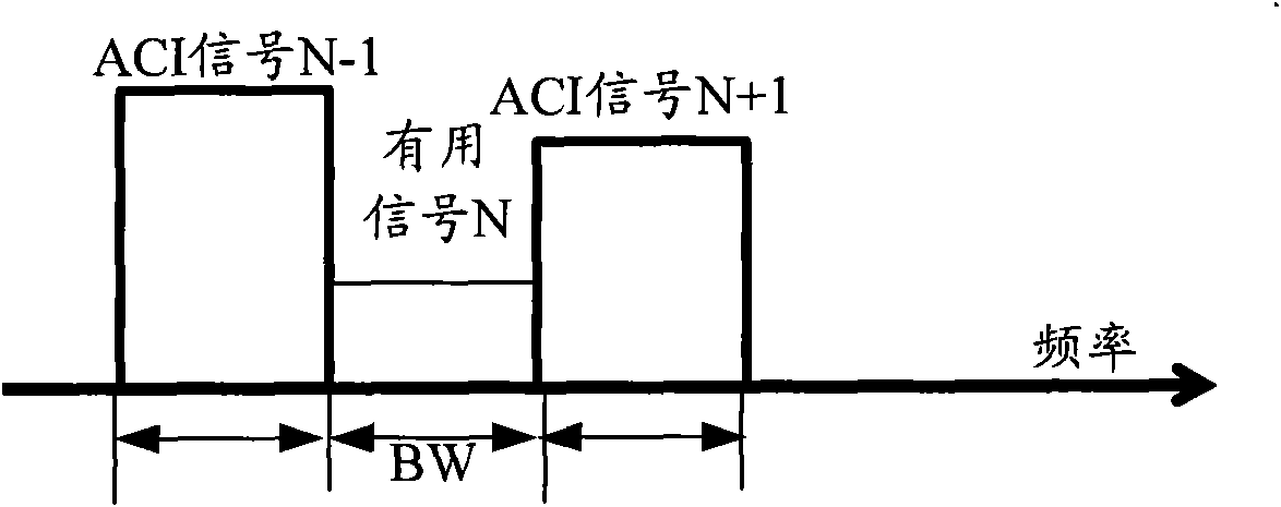
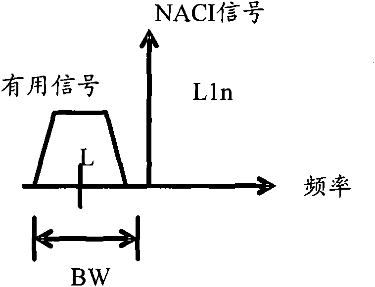
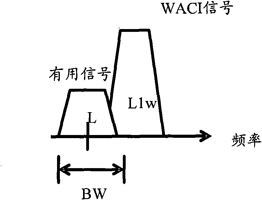
[0092] Aiming at the problems existing in the prior art, a brand-new interference signal detection scheme is proposed in the present invention, that is, at first the received radio frequency (RF) signal is divided into I and Q two-way signals, and the two-way signals can have the same bandwidth , but the phase is set to a difference of 90 degrees; then, the I channel signal is input to the first low-pass filter (LPF, Low Pass Filter), and the Q channel signal is input to the second LPF, and the bandwidth of the first LPF is always set to be greater than that of the second LPF. The bandwidth of two LPFs (the starting frequency of the bandwidth of two LPFs is the same); Afterwards, judge whether the total power of the filtered I-way signal output by the first LPF is greater than the total power of the Q-way signal after the filter output by the second LPF , and determine whether the comparison value of the total power of the two signals is greater than a preset ACI determination ...


PUM


Abstract

The invention discloses a method and a device for detecting interference signals. The method comprises the following steps: dividing received radio-frequency signals into two paths: I and Q, and differing the phases of the two paths of signals by 90 degrees; inputting the signals of the I path to a first LPF, inputting the signals of the Q path to a second LPF, and setting the bandwidth of the first LPF to be always greater than that of the second LPF; judging whether the total power of the signals of the I path, which are outputted by the first LPF after filtering is greater than the total power of the signals of the Q path, which are outputted by the second LPF after filtering, and judging whether the comparison value of the total power of the two paths of signals is greater than a preset ACI determination threshold; and if so, determining that ACI signals exist. The invention has simple hardware structure and simple and convenient implementation.

Description

technical field [0001] The invention relates to detection technology, in particular to a method and device for detecting interference signals. Background technique [0002] In a zero-IF receiver (DCR, Direct Conversion Receiver), due to various reasons, various interference signals may appear, such as Adjacent Channel Interference (ACI, Adjacent Channels Interference) and the like. [0003] The ACI signal is located in a frequency band adjacent to the frequency band occupied by the desired signal. The desired signal mentioned here refers to a signal that needs to be processed by a zero-IF receiver. figure 1 It is a schematic diagram of the relationship between the existing ACI and the desired signal. Such as figure 1 As shown, assuming that N represents the desired signal, then N−1 and N+1 represent the ACI signal respectively; the ACI signal usually has the same bandwidth (BW, Bandwidth) as the desired signal. [0004] In addition, the ACI signal can be further divided ...

Claims


Application Information

Patent Timeline
IPC IPC(8): H04B17/00H04B17/345
Inventor 张辉王西强林韶正薛梓建陈信宇熊伟
Owner 新奇点智能科技集团有限公司
Why Eureka
Try Eureka