Heat exchanger and heat exchanging device including same

A technology of heat exchangers and headers, applied in heat exchange equipment, heat exchanger shells, evaporators/condensers, etc., can solve problems such as uneven distribution of refrigerants and affecting the heat transfer effect of refrigerants

Inactive Publication Date: 2010-02-03
SANHUA HANGZHOU MICRO CHANNEL HEAT EXCHANGER
View PDF0 Cites 17 Cited by
  • Summary
  • Abstract
  • Description
  • Claims
  • Application Information

AI Technical Summary

Problems solved by technology

[0007] When the refrigerant flows inside the header 12 or the flat tubes 11, gas-liquid stratification will occur, the liquid refrigerant will gather at the bottom of the header 12 or the flat tubes 11, and the gaseous refrigerant will be located at the bottom of the header. The top of the tube 12 or the flat tube 11 leads to uneven distribution of the refrigerant, which affects the heat transfer effect of the refrigerant
[0008] at the same time, figure 1 The heat exchanger shown is a multi-circuit heat exchanger. Obviously, when the heat exchanger is a single-circuit heat exchanger, the two-phase refrigerant will also produce gas-liquid stratification inside the header 12 or each flat tube 11. phenomenon, resulting in uneven distribution of the refrigerant in the header 12 or each flat tube 11, which will also affect the heat exchange effect of the refrigerant

Method used


Image

  • Heat exchanger and heat exchanging device including same
  • Heat exchanger and heat exchanging device including same
  • Heat exchanger and heat exchanging device including same

Examples


Embodiment Construction

[0036] The core of the present invention is to provide a heat exchanger, which can make the refrigerant evenly distributed inside the header and each flat tube, thereby improving the heat exchange performance of the heat exchanger. Another core of the present invention is to provide a heat exchange device comprising the above heat exchanger.

[0037] In order to enable those skilled in the art to better understand the technical solutions of the present invention, the present invention will be further described in detail below in conjunction with the accompanying drawings and specific embodiments.

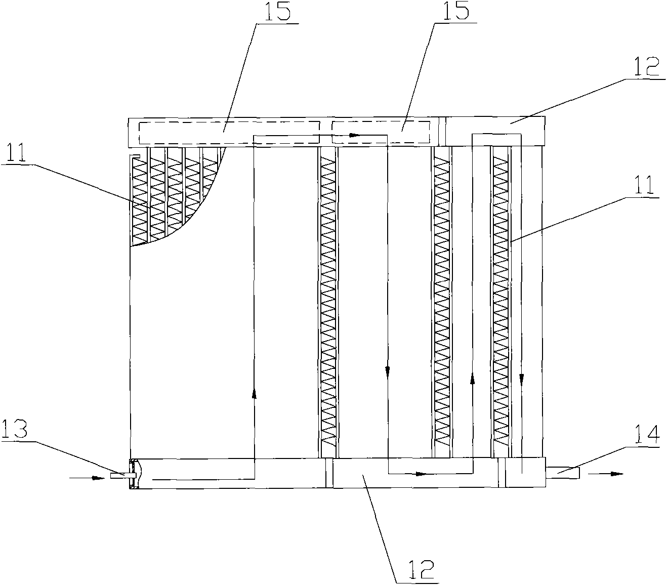
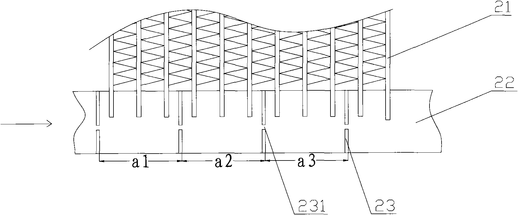
[0038] Please refer to figure 2 , figure 2 It is a schematic structural diagram of a heat exchanger in an embodiment of the present invention.

[0039] In the first embodiment, the heat exchanger provided by the present invention includes several flat tubes 21 , a header 22 communicating with each flat tube 21 , and an inlet tube and an outlet tube communicating with the header ...


PUM


Abstract

The invention discloses a heat exchanger comprising a plurality of flat pipes (21), a collecting pipe (22) communicated with the flat pipe (21), an inlet pipe and an outlet pipe which are communicatedwith the collecting pipe (22). A plurality of clapboards (23) are arranged inside the collecting pipe (22) along the flowing direction of refrigerant, and a proper distance is left between the adjacent clapboards (23); and each of the clapboards (23) is provided with a passage (231) with a total equivalent diameter less than the geometric diameter of the collecting pipeline. The heat exchanger ensures that the refrigerant is mixed evenly inside the collecting pipe (22) and then evenly distributed into respective flat pipe (21) so as to improve the heat exchanging performance. Besides, the invention also discloses a heat exchanging device including the heat exchanger.

Description

technical field [0001] The invention relates to the technical field of refrigeration, in particular to a heat exchanger; the invention also relates to a heat exchange device comprising the above heat exchanger. Background technique [0002] The heat exchange device in the prior art generally includes basic components such as a condenser, an evaporator, a compressor, and a throttle valve. The above basic components are connected in sequence through pipelines to form a closed system, and the refrigerant circulates in this closed system. , a state change occurs, thereby exchanging heat with the outside world to achieve the cooling effect. [0003] Among the basic components included in the heat exchange device, the condenser and the evaporator are the basic heat exchange components, and their structures are basically the same, collectively referred to as heat exchangers. [0004] Please refer to figure 1 , figure 1 It is a structural schematic diagram of a typical heat excha...

Claims


Application Information

Patent Timeline
Patent Type & Authority Applications(China)
IPC IPC(8): F25B39/00F28F9/22
Inventor 刘华钊黄宁杰
Owner SANHUA HANGZHOU MICRO CHANNEL HEAT EXCHANGER
Why Eureka
Try Eureka