
Tray of optical disk device and optical disk device including the same

A technology for optical disc devices and trays, which is applied in the direction of instruments, record carrier structural parts, data recording, etc., can solve the problems of turbulent air flow and the inability to fully reduce air sound, and achieve the effect of reducing air sound

Active Publication Date: 2010-02-03
HITACHI-LG DATA STORAGE
View PDF1 Cites 0 Cited by
  • Summary
  • Abstract
  • Description
  • Claims
  • Application Information

AI Technical Summary

Problems solved by technology

Since the flow of air is disordered on the side of the inclined surface being hit, the airborne noise cannot be sufficiently reduced.

Method used


Image

  • Tray of optical disk device and optical disk device including the same
  • Tray of optical disk device and optical disk device including the same
  • Tray of optical disk device and optical disk device including the same

Examples


Embodiment Construction

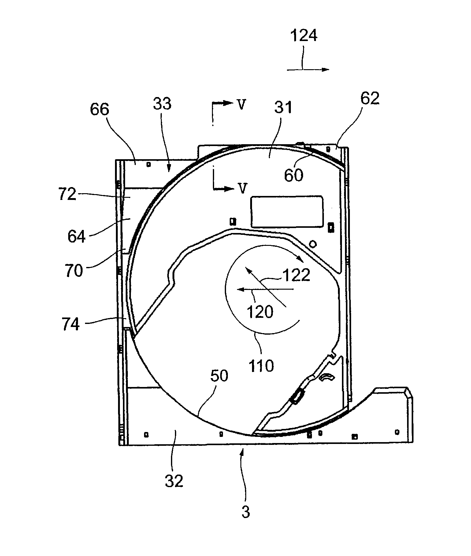
[0022] A tray of an optical disc device according to a preferred embodiment of the present invention will be described with reference to the drawings. In addition, in order to make the description easy to understand in the drawings, the thickness, size, scale, etc. of each member described in some parts do not match the actual ones. In addition, it is assumed in the description that the optical disc loaded in the optical disc device rotates clockwise, and it is assumed that the optical disc is inserted from the front.

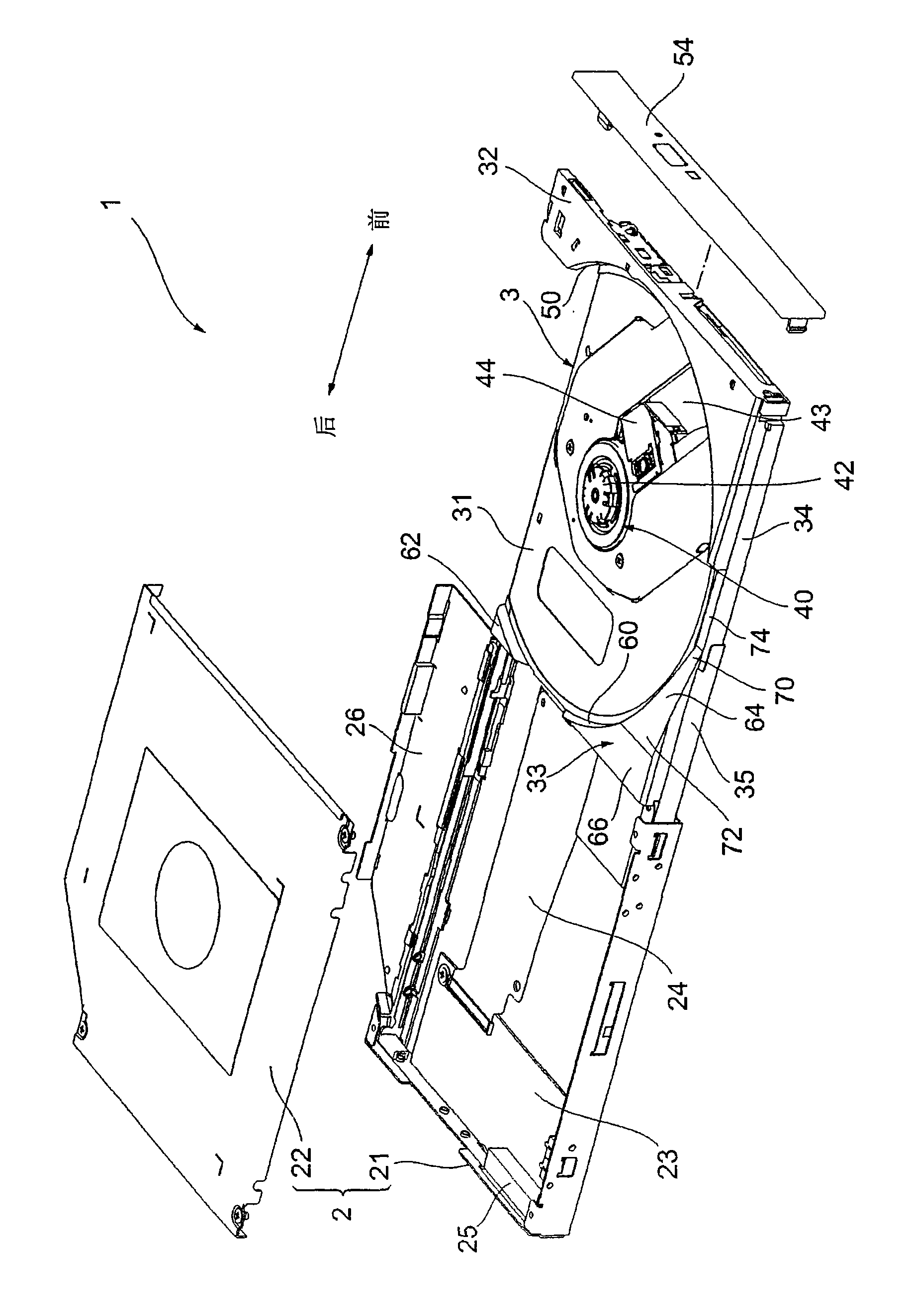
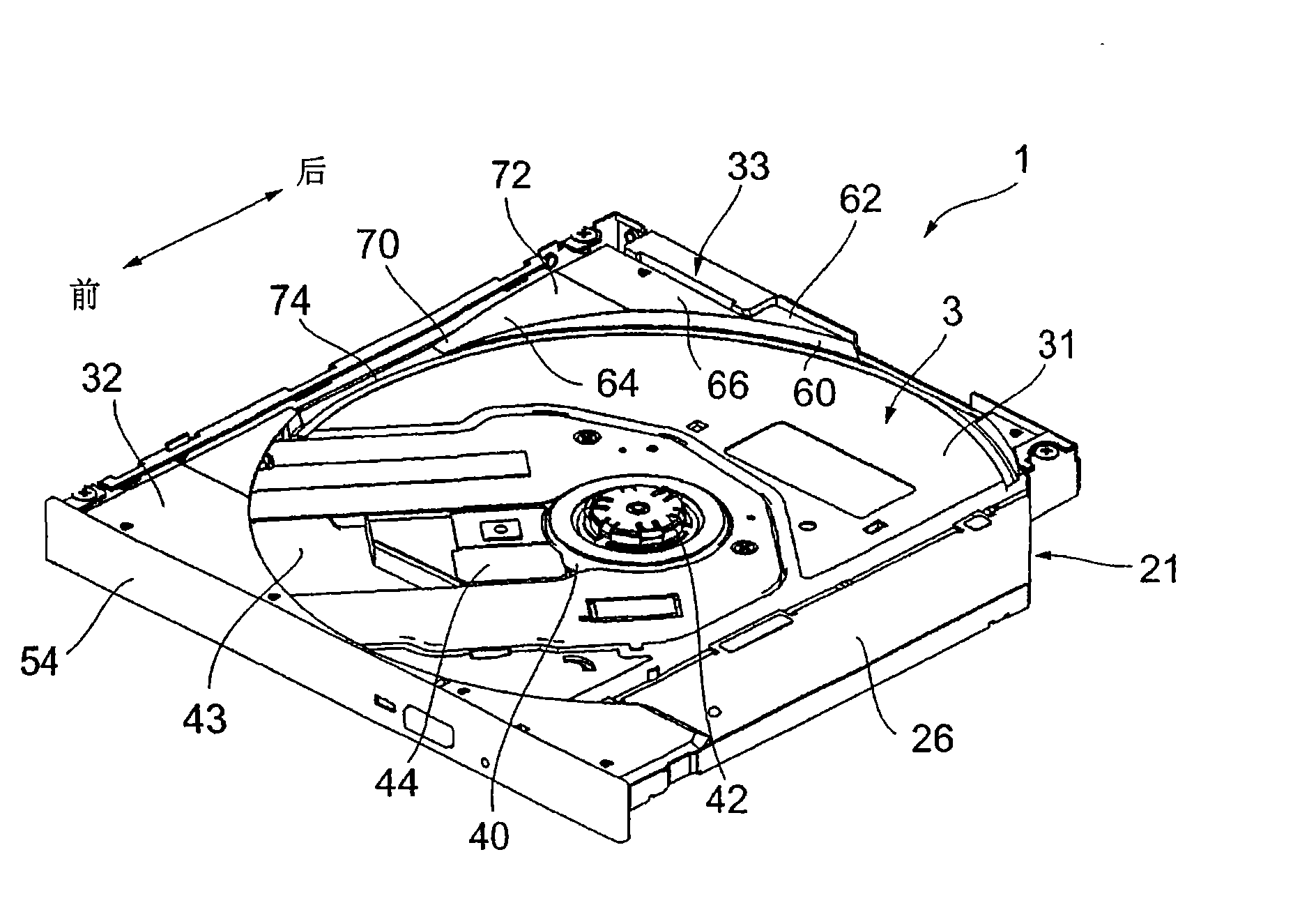
[0023] Such as figure 1 with figure 2 As shown, the optical disc device 1 has a housing 2 and a tray 3 detachably provided in the housing 2 . The frame body 2 has a box shape composed of a bottom box 21 and a top box 22. The tray 3 is inserted into the frame body 2 from an opening located on the front side (hand side) of the frame body 2, and the tray is drawn out (drawn out) from the frame body 2. 3. The bottom box 21 and the top box 22 are fixed by screw...


PUM


Abstract

A tray of an optical disk device and an optical disk device including the tray are provided. In a tray rear portion (33) located at a higher level than a tray bottom portion (31), a first tapered surface (60) as a draft taper and a second tapered surface (64) sloping more gently than the first tapered surface (60) are formed. An upper end (72) of the second tapered surface (64) is located fartherfrom a center of rotation of an optical disk (100) than a lower end (70), and thus air in a peripheral portion of the optical disk (100) generated during rotation of the disk is introduced along the tapered surface (64) to a rear.

Description

technical field [0001] The present invention relates to a tray suitable for muting an optical disc device. Background technique [0002] Such an optical disk device mounts an optical disk such as a CD or DVD on a tray, and reproduces or records data by rotating the optical disk. In recent years, as the rotational speed of optical discs has increased, there has been a problem that disc wind (air noise), which is noise, has become louder. For example, Patent Document 1 describes solving this problem by using a tray structure. [0003] The tray has a mounting portion on which an optical disc is mounted, and a front portion and a rear portion that are one step higher around the mounting portion. An opening for the optical pickup is formed from the center of the mounting portion (rotation center of the optical disk) to a part of the rear, and an inclined surface is formed on the edge of the opening to suppress airborne noise accompanying the rotation of the optical disk. The i...

Claims


Application Information

Patent Timeline
Patent Type & Authority Applications(China)
IPC IPC(8): G11B17/053
CPCG11B17/056G11B33/148
Inventor 桐原聪二郎山岸浩松本高路
Owner HITACHI-LG DATA STORAGE
Learn More