Blow-by gas treatment device for internal combustion engine

a treatment device and internal combustion engine technology, applied in the direction of combustion air/fuel air treatment, machines/engines, mechanical equipment, etc., can solve the problem of error in measuring the amount of intake air, and achieve the effect of reducing the propagation of pressure pulsation from the crankcase side to the intake air passage side, and reducing the noise of intake air

Active Publication Date: 2016-06-09
NISSAN MOTOR CO LTD
View PDF3 Cites 0 Cited by
  • Summary
  • Abstract
  • Description
  • Claims
  • Application Information

AI Technical Summary

Benefits of technology

[0009]The resonator is connected to the intake air passage, as the so-called Helmholtz type resonator element, to contribute to a reduction of intake air noise. The fresh air introduction passage is arranged to communicate with the intake air passage through the resonator, so that a fresh air is to flow from the intake air passage through the resonator into the fresh air introduction passage. Meanwhile, at the time when blow-by gas flows backwardly in a high load region, the blow-by gas is to flow from the fresh air introduction passage through the resonator into the intake air passage.
[0010]In the present invention, an orifice is provided at the fresh air introduction passage or at a connected section disposed between of the fresh air introduction passage and the r...

Problems solved by technology

In such an arrangement where the fresh air introduction passage is connected to between the throttle vale of the intake air passage and the air flow meter, a periodical change in pressure within the crankcase o...

Method used


Image

  • Blow-by gas treatment device for internal combustion engine
  • Blow-by gas treatment device for internal combustion engine
  • Blow-by gas treatment device for internal combustion engine

Examples


Embodiment Construction

[0017]Referring now to the accompanying drawings, an embodiment of the present invention will be discussed in detail.

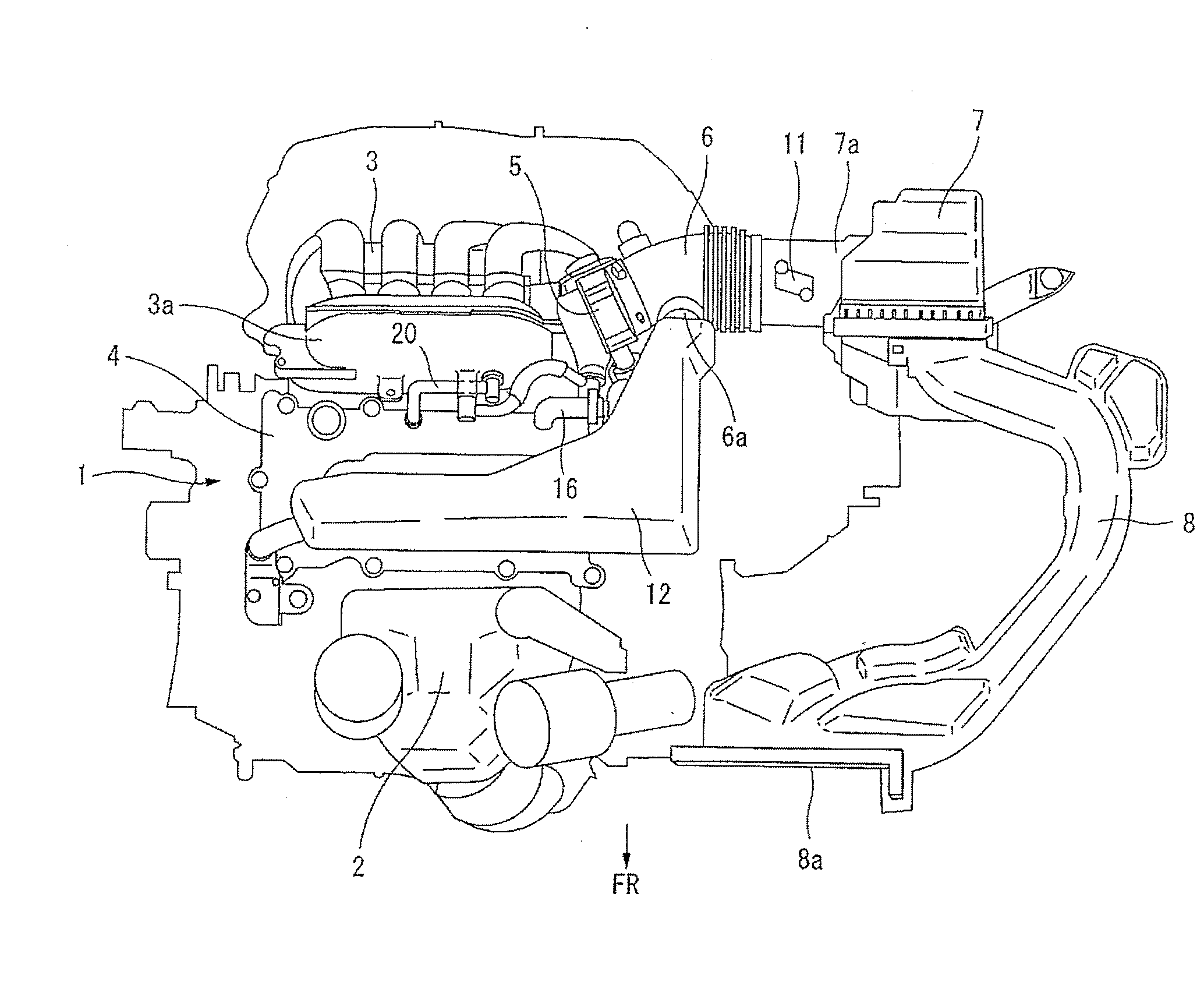
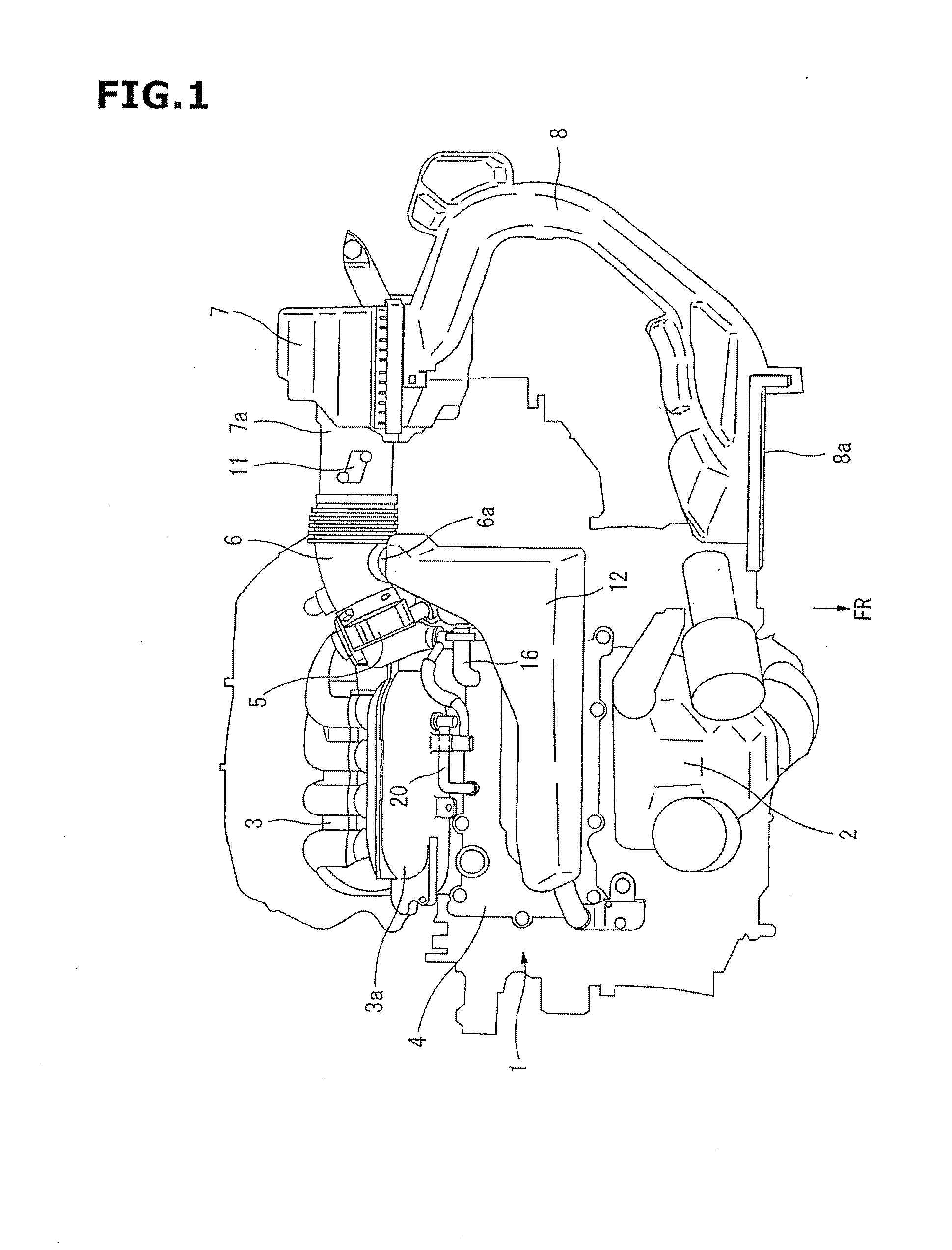
[0018]FIG. 1 is a plan view showing an automotive internal combustion engine 1 equipped with a brow-by gas treatment device according to the present invention, including an air intake system. The internal combustion engine 1 is mounted in an engine compartment disposed on the front side of a vehicle, in the so-called transverse posture (or an arrangement bringing the center axis of a crank shaft into line with the vehicle width direction). An exhaust manifold 2 is located on the front side of the vehicle (indicated in the drawing by “FR”) while an intake manifold 3 is located on the rear side of the vehicle. A collector portion 3a serving as a part of the intake manifold 3 is disposed adjacent to a cylinder head cover 4 on the rear side of the vehicle from the cylinder head cover 4. The collector portion 3a has an inlet portion at one longitudinal end, to which a thro...


PUM


Abstract

A resonator (12) for reducing intake air noise is connected to an intake air duct (6) connecting a throttle chamber (5) and an air cleaner case (7). This blow-by gas treatment device is equipped with a fresh air introduction passage comprising a fresh air introduction hose (16), and, a blow-by gas passage comprising a blow-by gas hose (20), with the fresh air introduction hose (16) connecting a cylinder head cover (4) and the resonator (12). A connector part (15) of the resonator (12) to which the fresh air introduction hose (16) is connected is provided with an orifice (21) formed integral with a lower body (13) formed of a synthetic resin, as a part thereof. Pulsation is effectively reduced by the throttling effect of the orifice (21) and the expansion effect of the resonator (12).

Description

TECHNICAL FIELD[0001]The present invention relates to an improvement of a blow-by gas treatment device for an internal combustion engine, the device being so adapted that brow-by gas in a crankcase of an internal combustion engine is led into an air intake system and then burned in a combustion chamber.BACKGROUND OF THE INVENTION[0002]In Patent Document 1, there is disclosed a brow-by gas treatment device for an internal combustion engine, the device comprising a fresh air introduction passage for introducing a fresh air into a crankcase from the upstream side (with respect to a throttle valve) of an intake air passage and a blow-by gas passage for emitting blow-by gas from the crankcase into the downstream side (with respect to the throttle valve) of the intake air passage. One end of the fresh air introduction passage is connected to between the throttle valve of the intake air passage and an air flow meter disposed upstream therefrom.[0003]In the thus constructed blow-by gas trea...

Claims


Application Information

Patent Timeline
IPC IPC(8): F02M25/06F01M11/08
CPCF01M11/08F02M25/06F01M13/022F01M13/028F01M13/0416F01M2013/0488F02M35/10222F02M35/1261F02M35/1288Y02T10/12
Inventor IKEGAYA, KIYOSHI
Owner NISSAN MOTOR CO LTD
Why Eureka
Try Eureka