Speaker

a technology of speaker and spherical tube, which is applied in the field of speakers, can solve the problems of increasing the rate of air passing through the groove, inability to obtain the dissipation effect, and inability to achieve the dissipation effect, so as to reduce the noise of air leakage to the outside, easy to dissipate, and the effect of large opening capacity

Active Publication Date: 2020-03-17
ALPINE ELECTRONICS INC
View PDF9 Cites 0 Cited by
  • Summary
  • Abstract
  • Description
  • Claims
  • Application Information

AI Technical Summary

Benefits of technology

[0011]The present invention solves the above-described problems of the related art, and an object of the present disclosure is to provide a speaker capable of providing a sufficient heat dissipating effect and reducing air noise by forming an air passage for generating an airflow so that the air passage faces a voice coil over the entire circumference thereof.
[0021]According to the speaker of the present disclosure, it is not necessary to form grooves or the like in a member of the support body, and the gap can be formed so as to face the outer periphery of the voice coil over a large area. The gap that faces the voice coil over substantially the entire circumference thereof has a large opening capacity. Therefore, when the vibrating plate vibrates, heat radiated from the voice coil can be easily dissipated to the outside. In addition, the air suction noise and air discharge noise generated when the vibrating plate vibrates can be reduced, and air noise that leaks to the outside can be reduced accordingly.

Problems solved by technology

(1) Since cooling airflows are formed in a plurality of narrow, shallow grooves, sufficient heat dissipating effect cannot be obtained. In addition, heat is dissipated from the above-described space unevenly between the regions in which the grooves are formed and regions in which no grooves are formed.
(2) When the vibrating plate vibrates in the front-back direction, air passes through the narrow, shallow grooves. Therefore, when the amplitude of the vibrating plate increases, the flow rate of the air that passes through the grooves increases, and air suction noise and air discharge noise increase accordingly. The air suction noise and air discharge noise easily leak to the outside as air noise.
(3) In the speaker according to Patent Document 1, a plurality of grooves need to be formed in the plate. In the speaker according to Patent Document 2, a plurality of grooves need to be formed in the spacer. Accordingly, the processing cost is increased.

Method used


Image

  • Speaker
  • Speaker
  • Speaker

Examples


first embodiment

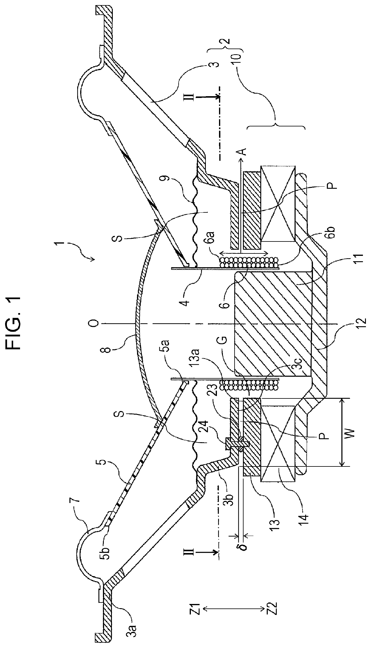
[0025]FIG. 1 illustrates a speaker 1 according to the present invention.

[0026]The speaker 1 includes a frame 3 and a magnetic circuit unit 10 fixed at the back (Z2-side) of the frame 3. The frame 3 and the magnetic circuit unit 10 form the support body 2.

[0027]The frame 3 is formed of a non-magnetic material or a magnetic material by, for example, die-casting by using a metal, injection molding by using a synthetic resin, or sheet metal working by using a metal sheet.

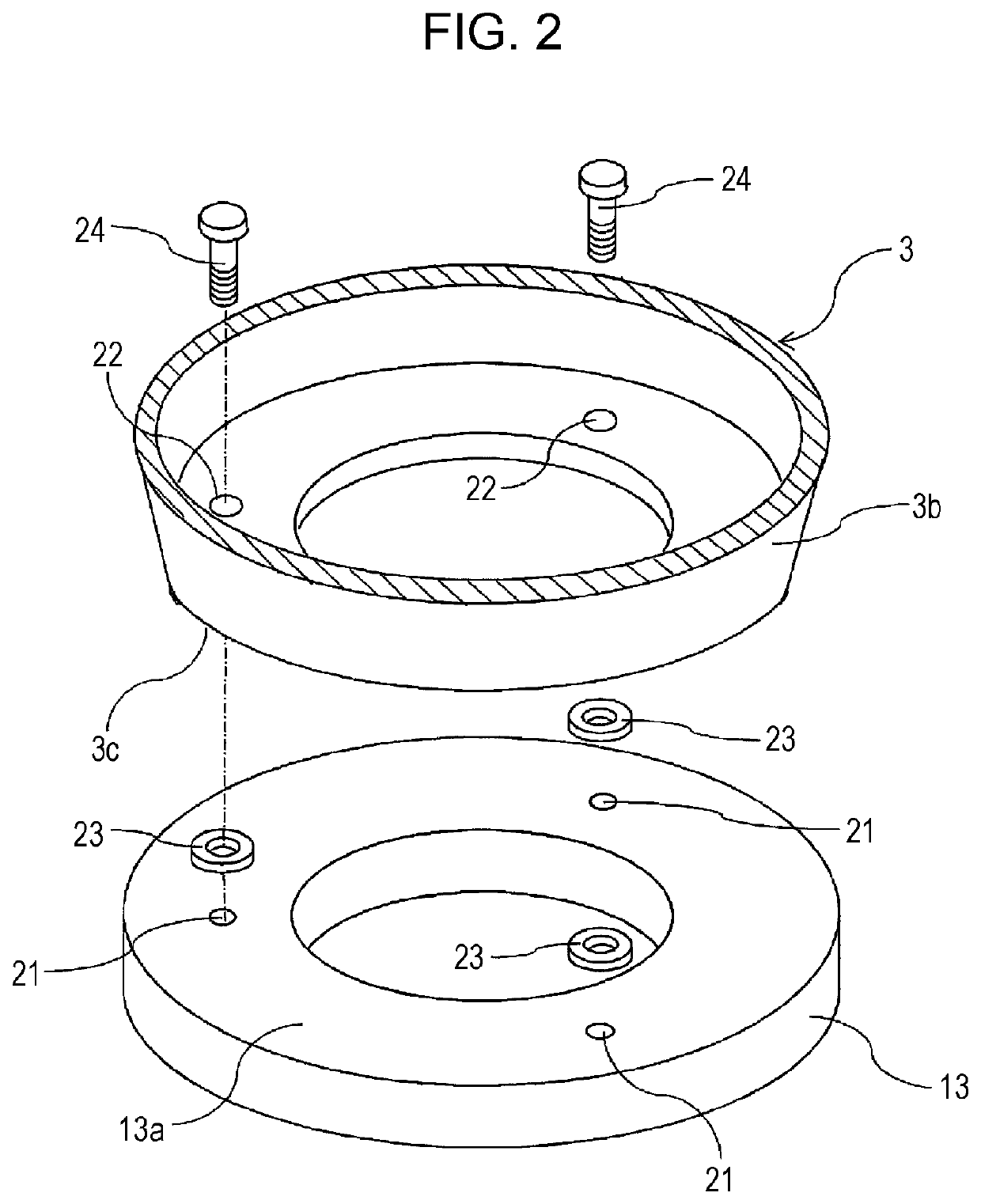
[0028]The magnetic circuit unit 10 includes a center pole 11 located at the center, a bottom yoke 12 fixed to the back (Z2-side) of the center pole 11, a top yoke 13 that faces the front (Z1-side) of an outer peripheral portion of the bottom yoke 12, and a magnet 14 fixed between the bottom yoke 12 and the top yoke 13. The center pole 11, the bottom yoke 12, and the top yoke 13 are formed of a magnetic metallic material. The magnet 14 is a ring-shaped permanent magnet, and has a center hole in which the center pole 11 i...

second embodiment

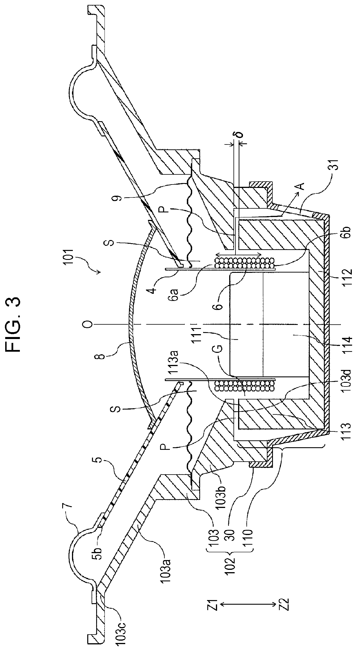
[0043]FIG. 3 illustrates a speaker 101 according to the present disclosure. Components of the speaker 101 that are the same as those of the speaker 1 illustrated in FIG. 1 are denoted by the same reference numerals. In the speaker 101 illustrated in FIG. 3, a frame 103, a magnetic circuit unit 110, and a fixing member 30 form a support body 102.

[0044]The magnetic circuit unit 110 illustrated in FIG. 3 includes a bottom yoke 112 having the shape of a cylinder with a bottom. A magnet 114 is fixed to the front surface of a central portion the bottom yoke 112, and a center pole 111 is fixed to the front of the magnet 114. The magnet 114 has a solid cylindrical shape, and is magnetized so that a front surface (Z1-side surface) and a back surface (Z2-side surface) thereof have different magnetic poles. A magnetic gap G is formed between an inner peripheral surface of a tubular portion 113 of the bottom yoke 112 and an outer peripheral surface of the center pole 111. A voice coil 6, which ...


PUM


Abstract

A speaker includes spacers that are disposed between a front end portion of a top yoke, which serves as a first member, and a back end portion of a back portion of a frame, which serves as a second member, to form a gap that defines an air passage. When a bobbin and a vibrating plate vibrate in a front-back direction, an airflow through the air passage, which faces a voice coil, is formed between the space around a magnetic gap and the outside. Accordingly, the voice coil is cooled over the entire circumference thereof.

Description

RELATED APPLICATION[0001]The present application claims priority to Japanese Patent Application Number 2017-176975, filed Sep. 14, 2017, the entirety of which is hereby incorporated by reference.BACKGROUND1. Field of the Invention[0002]The present invention relates to a speaker having a structure capable of reducing a temperature increase due to heat generated by a voice coil.2. Description of the Related Art[0003]Japanese Unexamined Patent Application Publication No. 8-102994 (hereinafter referred to as Patent Document 1) and Japanese Unexamined Utility Model Registration Application Publication No. 64-40995 (hereinafter referred to as Patent Document 2) describe speakers for reducing a temperature increase due to heat generated by a voice coil.[0004]The speaker described in Patent Document 1 includes a magnetic circuit unit including a back plate, a center pole provided at the center of the back plate, a magnet fixed to an outer peripheral portion of the back plate, and a top plat...

Claims


Application Information

Patent Timeline
Patent Type & Authority Patents(United States)
IPC IPC(8): H04R9/02H04R9/04H04R7/02H04R7/18H04R9/06H04R7/06
CPCH04R7/18H04R9/022H04R9/025H04R9/04H04R9/06H04R7/02H04R2400/11
Inventor TANABE, KEI
Owner ALPINE ELECTRONICS INC
Why Eureka
Try Eureka