
Push rod device for electromagnet

A push rod device, electromagnet technology, applied in the direction of electromagnets, etc., can solve the problems of complex production process and residual magnetism

Inactive Publication Date: 2010-02-03
敬德元
View PDF0 Cites 2 Cited by
  • Summary
  • Abstract
  • Description
  • Claims
  • Application Information

AI Technical Summary

Problems solved by technology

With this design, the main body of the high-carbon steel push rod is used to generate magnetism after electrification; the copper connector is used to isolate the magnetic field and instantly eliminate the residual magnetism; this overcomes the problem that the current electromagnet will generate residual magnetism and accumulate residual magnetism Disadvantages: After power on, use the coil with current to generate a magnetic field around the main body of the push rod, thereby generating magnetism; after power off, because copper has the function of magnetic isolation and degaussing, when the power is off, the copper connector will The remaining magnetism in the high carbon steel of the push rod body is quickly eliminated, there is no residual magnetism, the stability and reliability of the electromagnet are enhanced, and the life of the electromagnet is extended, which solves the problem of the electromagnet push rod device currently used when the power is turned off. The problem of residual magnetism and residual magnetism still occurs; the production process is simple through two-stage separation, and the flexibility of the electromagnet can be effectively controlled, which solves the problem of complicated production process of the currently used electromagnet push rod device

Method used


Image

  • Push rod device for electromagnet
  • Push rod device for electromagnet

Examples


Embodiment Construction

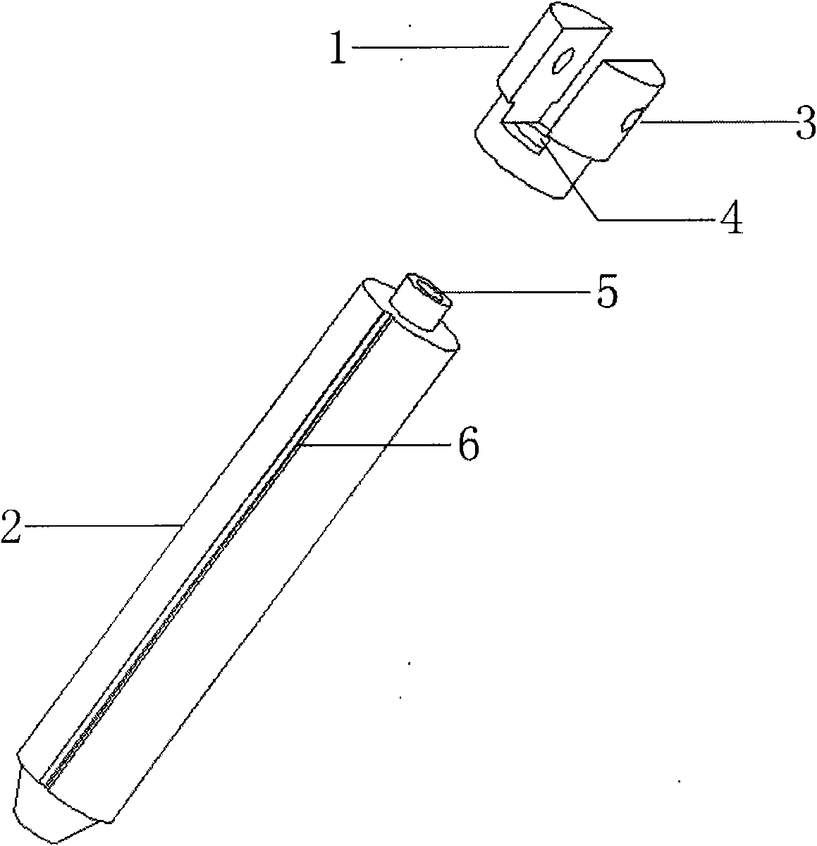
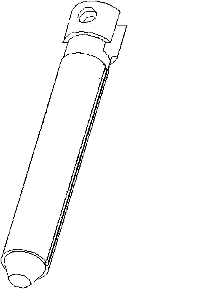
[0007] As shown in the figure: the push rod is composed of a connector 1 and a push rod main body 2; There is an exhaust groove 6 from top to bottom, which is used for exhausting when the push rod is in motion; the connector 1 is made of copper, and the lower end of the connector 1 is made with a connecting hole 4, and the fixing column 5 is inserted into the connecting hole 4 , and connect and fix the connector 1 and the push rod body 2 by punching, the positioning groove in the middle of the upper end of the connector 1 divides the upper end of the connector 1 into two independent ears, and a connecting hole 3 is formed at each end for Fixed push part connection.

[0008] In this way, the push rod is divided into two sections. The material used for the connector 1 is copper, and the material used for the push rod body 2 is high carbon steel. The connector 1 and the push rod body 2 are combined by stamping. When the power is turned on, the push rod body 2 to produce magnetis...


PUM


Abstract

The invention relates to a push rod device for an electromagnet, in particular to a push rod device for the electromagnet, which can eliminate residual magnetism instantly without remaining the residual magnetism after power turn-off and effectively control the flexibility and the stability of the electromagnet. The push rod device for the electromagnet comprises two separated sections, namely thepush rod is divided into a push rod main body and a connector, wherein the push rod main body is made of a high-carbon steel material, the head of the main body is provided with a fixed column, and the push rod main body is provided with an air discharge duct from top to bottom; and the connector is made of a copper material, the lower end of the connector is provided with a connecting hole, thefixed column is arranged in the connecting hole, and the push rod main body and the connector are fixed together by stamping. Thus, the push rod device for the electromagnet has the advantages of reasonable structure, high stability and strong reliability, can eliminate the residual magnetism instantly, and can effectively control the flexibility of the electromagnet.

Description

technical field [0001] The invention relates to a push rod device of an electromagnet, especially an electromagnet designed to eliminate the residual magnetism, eliminate the residual magnetism instantly after the power is cut off, leave no residual magnetism, and effectively control the flexibility and stability of the electromagnet push rod device. technical background [0002] The electromagnet push rod device currently used is made of high-carbon steel. The main body of the push rod and the connector are made of the same material, and the two are an integral device; the operating principle of the device is: , a magnetic field is generated around the coil with current, which makes the high-carbon steel magnetic; after the power is turned off, the magnetism disappears; because all the materials used in this technology are high-carbon steel, there are certain defects; because high-carbon steel is easy to magnetize, resulting in Residual magnetism, the longer the time, the ...

Claims


Application Information

Patent Timeline
IPC IPC(8): H01F7/06
Inventor 敬德元
Owner 敬德元
Learn More