Data merging and receiving method based on uplink coordinated multipoint

A receiving method and data technology, applied in the direction of digital transmission system, network traffic/resource management, electrical components, etc., can solve the problem of X2 link transmission overhead burden, etc., to achieve the effect of ensuring performance and reducing transmission overhead

Active Publication Date: 2010-02-03
BEIJING UNIV OF POSTS & TELECOMM
0 Cites 31 Cited by

AI-Extracted Technical Summary

Problems solved by technology

But at this time, the X2 link tra...

Abstract

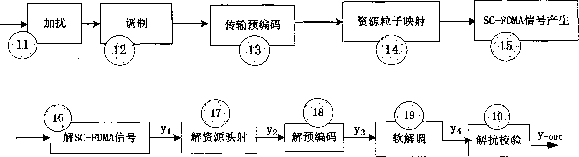
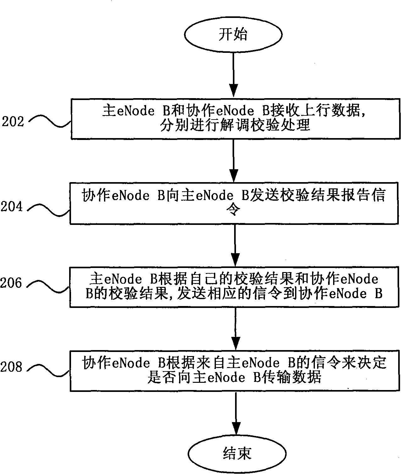
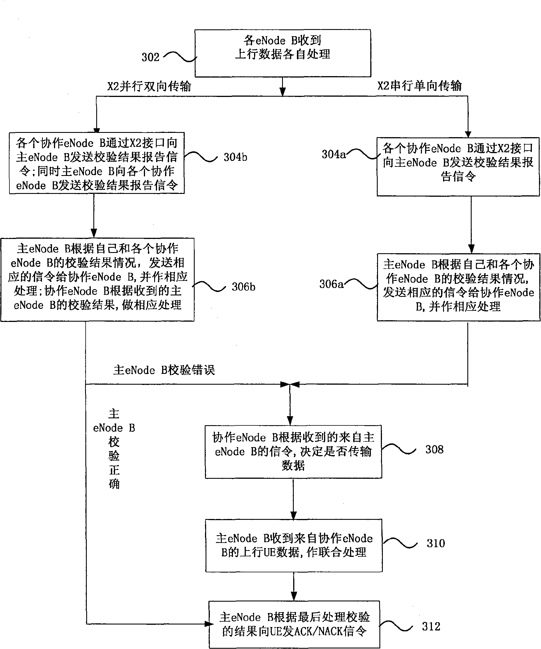
The invention discloses a coordinated multipoint data merging and receiving method used for an uplink CoMP scene, relating to an advanced long time evolution system (LTE-Advanced system) and a new technical point CoMP technology introduced into the LTE-Advanced system and mainly solving a problem concerning the multipoint uplink data reception in the CoMP scene which is different from a conventional cellular network. The method makes full use of the characteristics of CoMP uplink transmission and the separate data processing function of various dNode Bs, namely various coordinated cells conduct multipoint data reception and respectively demodulate the data. According to the verification of coordinated dNode Bs, master dNode Bs send corresponding signaling to the coordinated dNode Bs. The coordinated dNode Bs determine whether to transmit data to the master dNode Bs according to the signaling from the master dNode Bs. The master dNode Bs adopt an appropriate data transmitting and merging mode so as to reduce the transmission expenditure of an X2 interface and improve the uplink data transmission performance.

Application Domain

Technology Topic

Data functionData transmission +6

Image

  • Data merging and receiving method based on uplink coordinated multipoint
  • Data merging and receiving method based on uplink coordinated multipoint
  • Data merging and receiving method based on uplink coordinated multipoint

Examples

  • Effect test(4)

Test Example

[0087] Application example 1 (see Figure 7 ):
[0088] reference Image 6 As shown in the schematic diagram of the CoMP scenario of cooperation between eNode Bs, the primary eNodeB, the cooperative eNode B1 and the cooperative eNode B2 constitute CoMP and serve the user UE. See Figure 7 After the uplink CoMP transmission is performed, the process of data merging through cooperation between eNode Bs is:
[0089] ①Each eNode B in CoMP (including main eNode B 71, cooperative eNode B172, cooperative eNode B273) first carries out their own independent receiving end processing process (such as figure 1 The receiving end processing flow) to obtain the respective verification results.
[0090] ② X2 interface two-way transmission: the eNode B attached to each coordinated cell sends ACK/NACK signaling to the master eNode B through the X2 interface according to their respective verification results; at the same time, the master eNode B sends its verification results through the X2 interface ACK/NACK signaling to each cooperating eNode B.
[0091] ③After the master eNode B learns the verification results of the other two cooperating eNode Bs and the cooperating eNode B learns the verification results of the master eNode B:
[0092] (1) If the primary eNode B checks correctly, that is, when each cooperating eNode B receives the ACK signaling from the primary eNode B, the primary eNode B transmits the ACK signaling to the UE in the designated subframe, and then directly performs step ⑥; At the same time, each cooperative eNode B discards the uplink user data received at this time, and prepares to receive the next uplink data block.
[0093] (2) If the master eNode B has a check error, but at least one cooperating eNode B has a correct check, the master eNode B selects one of the cooperating eNode Bs that has the correct check (according to the distance criterion) and sends it a data transmission request indication T1, and send a data transmission rejection indication R to other cooperating eNode Bs. Here, when the master eNode B selects one of the cooperating eNode Bs with correct verification, the cooperating eNode B can report the arrival sequence of the signaling according to step ②, and the one that arrives early can be regarded as the one that is close to the master eNode B;
[0094] (3) If all eNode Bs have check errors, the master eNode B sends a data transmission request indication T2 to all cooperating eNodeBs.
[0095] ④ The cooperative eNode B decides whether to transmit data according to the received signaling instructions of the master eNode B:
[0096] (1) If receiving indication signaling T1, send hard decision information ( figure 1 The output signal y-out of step ⑤ of the receiving end flow chart);
[0097] (2) If the indication signaling N is received, the cooperative eNode B does not transmit data;
[0098] (3) If receiving the indication signaling T2, it needs to send uplink data to the primary eNode B. This data can include the received data without demodulation ( figure 1 The output signal y3 of step ③ of the receiving end flow chart), soft bit information ( figure 1 The output signal y4 of step ④ of the receiving end flowchart) or hard decision information ( figure 1 The output signal y-out of step ⑤ in the receiving end flow chart).
[0099] ⑤ The main eNode B performs joint processing and verification. The joint processing can adopt selective combination, equal gain combination or maximum ratio combination.
[0100] ⑥ The master eNode B sends ACK/NACK signaling to the UE in the designated subframe according to the final check result.

Test Example

[0101] Application example 2 (see Figure 8 ):
[0102] against Image 6 As shown in the schematic diagram of the CoMP scenario of cooperation between eNode Bs, the primary eNodeB, the cooperative eNode B1 and the cooperative eNode B2 constitute CoMP and serve the user UE. Such as Figure 8 As shown, after uplink CoMP transmission is performed, the process of data merging through cooperation between eNode Bs is:
[0103] In CoMP, each eNode B (including main eNode B 81, cooperative eNode B1 82, and cooperative eNode B2 83) first performs its own independent receiving end processing process (such as figure 1 Receiving end processing flowchart) to obtain the results of their respective verification.
[0104] X2 interface unidirectional transmission: The eNode Bs attached to each coordinated cell send the verification result ACK/NACK signaling to the master eNode B through the X2 interface according to their respective verification results.
[0105] According to the verification results of the three eNode Bs:
[0106] (1) If the master eNode B checks correctly, it sends R indication signaling to all cooperating eNode Bs, notifying cooperating eNode Bs that it is not necessary to transmit data through the X2 interface, and send ACK signaling to the UE in the designated subframe, that is, skip the step ④⑤Execute step ⑥ directly;
[0107] (2) If the master eNode B has a check error, but at least one cooperating eNode B has a correct check, the master eNode B selects one of the cooperating eNode Bs that has the correct check (according to the distance criterion) and sends it a data transmission request indication T1 , And send a data transmission rejection indication R to other cooperating eNode Bs. Here, when the master eNode B selects one of the cooperating eNode Bs with correct verification, the cooperating eNode B can report the arrival sequence of the signaling according to step ②, and the one that arrives early can be regarded as the one that is close to the master eNode B;
[0108] (3) If all eNode Bs have check errors, the master eNode B sends a data transmission request indication T2 to all cooperating eNodeBs.
[0109] The cooperative eNode B decides whether to transmit data according to the received signaling instructions from the master eNode B:
[0110] (1) If receiving indication signaling T1, send hard decision information ( figure 1 The output signal y-out of step ⑤ of the receiving end flow chart);
[0111] (2) If receiving indication signaling R, no data is transmitted;
[0112] (3) If receiving the indication signaling T2, it needs to send uplink data to the primary eNode B. This data can include the received data without demodulation ( figure 1 The output signal y3 of step ③ of the receiving end flow chart), soft bit information ( figure 1 The output signal y4 of step ④ of the receiving end flowchart) or hard decision information ( figure 1 The output signal y-out of step ⑤ in the receiving end flow chart).
[0113] The master eNode B performs joint processing and verification. The joint processing can adopt selective combination, equal gain combination or maximum ratio combination.
[0114] The primary eNode B sends ACK/NACK signaling to the UE.

Test Example

[0115] Application example 3 (see Picture 9 )
[0116] Picture 9 It is a CoMP scenario + MU-MIMO scenario for collaboration between eNode Bs. That is, three eNode Bs form CoMP to serve an edge user UE1. The difference from scenario two is that one of the cooperative eNode Bs forms MU-MIMO with UE1 and UE2.
[0117] Picture 9 For UE1, the primary eNode B, cooperative eNode B1, and cooperative eNode B2 form CoMP, and perform multi-point coordinated transmission and reception for UE1. At the same time, UE1 and UE2 form uplink MU-MIMO for cooperative eNode B1. In this CoMP+MU-MIMO scenario, the data received by the cooperative eNode B1 is no longer only the data of UE1, but the sum of the data of UE1 and UE2. That is, the uplink signal received by eNode B1 is expressed as y eNB1 =h 1 x 1 +h 2 x 2 , Where h 1 , H 2 Respectively represent the uplink channels from UE1, UE2 to eNode B1, x 1 , X 2 Represents the uplink data sent by UE1 and UE2 to eNode B1.
[0118] For the primary eNode B, the uplink data of UE1 needs to be obtained x 1 , The data consolidation and receiving process can take Figure 7 with Figure 8 Process. It’s just that when a cooperative eNode B is required to transmit data, for a cooperative eNode B with MU-MIMO, interference cancellation or suppression must be performed first to extract UE1 information (different from Figure 7 with Figure 8 The transmission content of the cooperative eNode B. This information cannot be directly the uplink data received by the cooperative eNode B, but can only be soft bit information or hard decision information), and then transmitted to the master eNode B through the X2 interface. The master eNode B finally performs joint processing to obtain the uplink data of UE1, and sends ACK/NACK signaling to UE1 in the designated subframe according to the check result. These processes are the same as application examples 2 and 3.

PUM

no PUM

Description & Claims & Application Information

We can also present the details of the Description, Claims and Application information to help users get a comprehensive understanding of the technical details of the patent, such as background art, summary of invention, brief description of drawings, description of embodiments, and other original content. On the other hand, users can also determine the specific scope of protection of the technology through the list of claims; as well as understand the changes in the life cycle of the technology with the presentation of the patent timeline. Login to view more.

Similar technology patents

Dynamic configuration method for process flow of equipment

PendingCN114565352AReduce transmission overheadImprove transmission efficiencyCharacter and pattern recognitionOffice automationData labelingPredictive analytics
Owner:GUILIN UNIV OF ELECTRONIC TECH

Information coding method, information decoding method, and devices

InactiveCN108173619AReduce encoding overheadReduce transmission overheadError preventionComputer hardwareReliable transmission
Owner:HUAWEI TECH CO LTD

Multi-party set synchronization method and device and electronic equipment

PendingCN111538865AShorten the transmission pathReduce transmission overheadOther databases indexingTransmissionReal-time computingDistributed computing
Owner:NAT UNIV OF DEFENSE TECH

Classification and recommendation of technical efficacy words

  • Reduce transmission overhead
  • Guaranteed performance

Cqi reporting method and apparatus for mobile telecommunication system

ActiveUS20100034114A1Reduce transmission overheadPower managementTransmission systemsTelecommunicationsMobile telecommunication systems
Owner:MIICS & PARTNERS JAPAN CO LTD

Correlating network transactions

ActiveUS20100268797A1Increase efficiency and scalableReduce transmission overheadError preventionTransmission systemsComputer programDistributed computing
Owner:EXFO

Preparing method for 6-series aluminum alloy sectional bar

InactiveCN105838938APrecise control of heating temperatureGuaranteed performanceAluminium alloyArtificial aging
Owner:广西南南铝加工有限公司

Aluminum die-casting alloy for digital electronic product

ActiveCN103526088AGuaranteed performanceSuppress deterioration of fatigue performanceAnodisationAlloy elementAnodic oxidation
Owner:苏州利达铸造有限公司
Why Eureka
Try Eureka