Delay mechanism for automatic injection device

一种自动注射、设备的技术,应用在自动注射器、注射器、皮下注射器械等方向

Inactive Publication Date: 2010-02-03
ELI LILLY & CO
View PDF1 Cites 29 Cited by
  • Summary
  • Abstract
  • Description
  • Claims
  • Application Information

AI Technical Summary

Problems solved by technology

While these solutions may work, they have their own disadvantages, for example, the delay mechanism is used to transmit force to the syringe during injection

Method used


Image

  • Delay mechanism for automatic injection device
  • Delay mechanism for automatic injection device
  • Delay mechanism for automatic injection device

Examples


Embodiment Construction

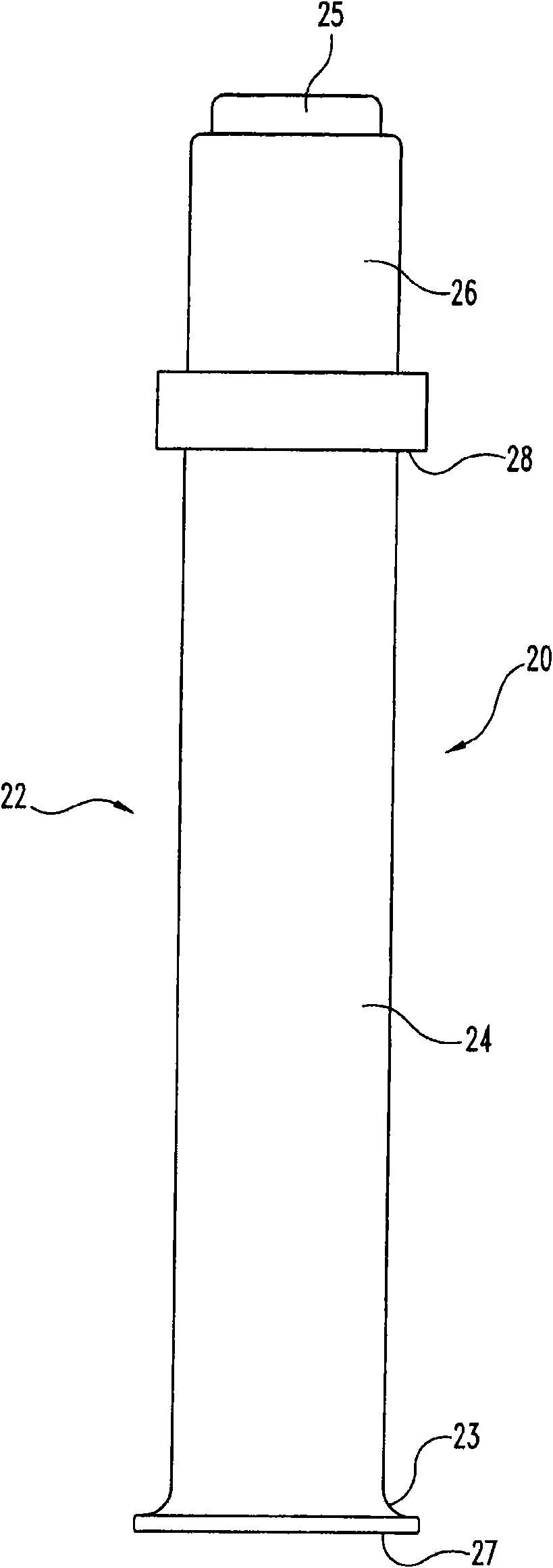
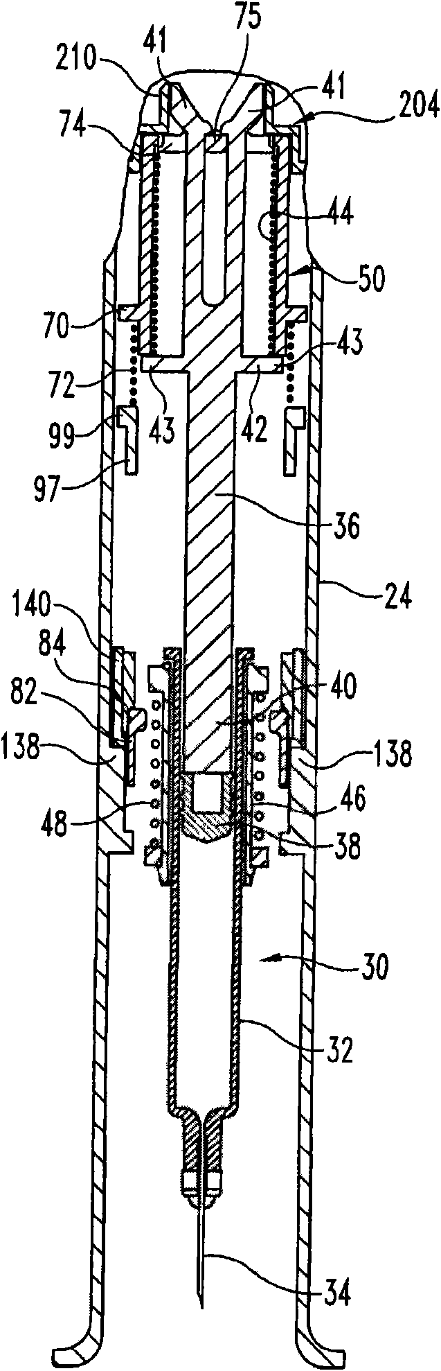
[0045] see now figure 1 and 2 , showing a front view and a cut-away partial front view, respectively, of an automatic injection device equipped with a first embodiment of the delay mechanism of the present invention. Since the delay mechanism of the present invention is advantageously applicable in a variety of different configurations of automatic injection devices, only limited injection device details are shown and described herein, which are intended to be illustrative and in no way limiting of the invention.

[0046] As with conventional designs, the automatic injection device, generally indicated at 20, has a trigger which, when actuated by the user, causes the needled syringe of the device to be driven downward, causing the injection needle to protrude beyond the lower end of the device housing. Penetrate the user. The device then proceeds to inject the medicament contents of the syringe through the needle, after which the syringe is retracted allowing the injection n...


PUM


Abstract

A delay mechanism for staging the operation of an automatic injection apparatus (20) to ensure medication contents are properly delivered prior to the needled syringe (32) of the apparatus being retracted. In one form, the delay mechanism includes a shuttle (50), a follower (110), a locking member, a damping compound, and a driver and a driver biasing element (44). The shuttle is for a needled syringe of the apparatus and includes a first latching element. The follower includes a second latching element and a cammable surface, which second latching element is for cooperating with the first latching element to limit motion of the shuttle relative to the follower in a second direction opposite the first direction. The locking member is movable from a locking position to a release position by engagement with the syringe plunger during an injection, the locking member, when in the locking position, preventing rotation of the follower relative to the shuttle, the locking member, when in the release position, allowing rotation of the follower relative to the shuttle. The damping compound is between the follower and a supporting surface to dampen rotation of the follower relative to the shuttle. The driver is rotatably fixed relative to the shuttle and includes a camming surface. The shuttle allowing retracting of the syringe needle into the housing of the automatic injection apparatus after injection.

Description

technical field [0001] The present invention relates to drug injection devices, and more particularly to a delay mechanism for an automatic injection device. Background technique [0002] Patients with many different diseases often have to self-inject the drug. Various devices have been developed to assist in these injections. One type of device is an automatic injection device. Devices of this type, when triggered by the user, cause the needle of the syringe provided in the housing of the device before triggering to be automatically inserted into the user's body and thereafter to automatically inject a dose of medicament through the inserted needle. Automatic injection devices of known type then automatically advance the shroud to cover the needle when the dose has been administered. In another type of automatic injection device, there is a more satisfactory configuration for some applications, wherein instead of an advancing shroud, the device will automatically retract...

Claims


Application Information

Patent Timeline
Patent Type & Authority Applications(China)
IPC IPC(8): A61M5/20A61M5/32
CPCA61M5/3202A61M5/3287A61M5/3204A61M5/2033A61M5/326A61M2005/3143A61M2005/2073A61M2005/206A61M5/32A61M5/20
Inventor A·B·詹姆斯R·I·利斯特P·J·西尔伯沙茨B·J·马森
Owner ELI LILLY & CO
Why Eureka
Try Eureka