
Transmission optical system

An optical system and imaging optics technology, applied in the field of transmission optical systems, can solve problems such as observation position constraints and aberrations

Active Publication Date: 2010-02-10
NAT INST OF INFORMATION & COMM TECH
View PDF3 Cites 4 Cited by
  • Summary
  • Abstract
  • Description
  • Claims
  • Application Information

AI Technical Summary

Problems solved by technology

However, since the relay lens system arranges all the lenses so that the optical axes are in a straight line and can transmit the image, there is a problem that the image formed by the objective lens is transmitted to a relatively free position by total reflection in a plurality of optical fibers. Compared with fiber optic endoscopes, etc., the observation position of the image is physically restricted
In addition, in such a relay lens system, even if the object to be projected is a three-dimensional object, there is a problem of aberration, and practically only two-dimensional images can be observed.

Method used


Image

  • Transmission optical system
  • Transmission optical system
  • Transmission optical system

Examples


no. 1 approach

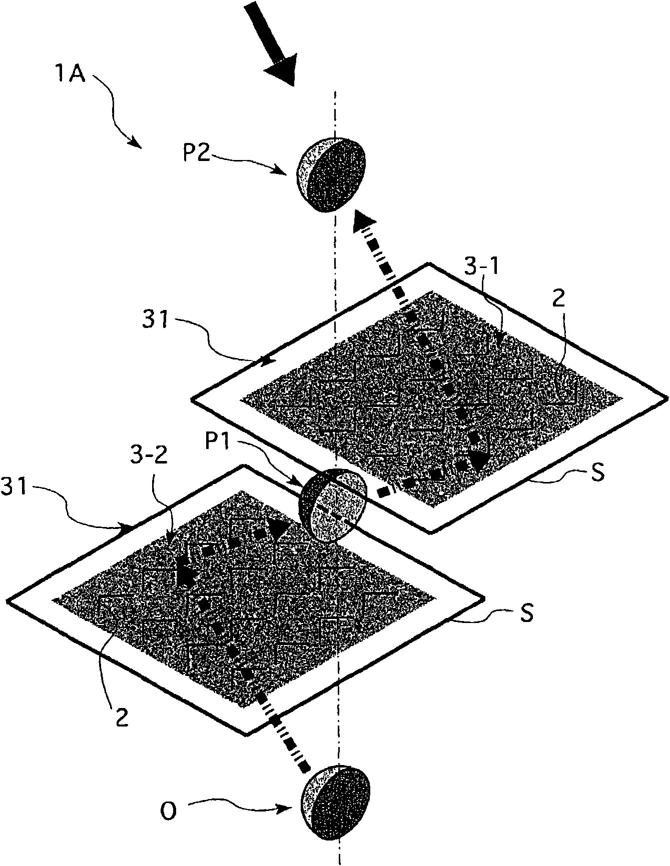
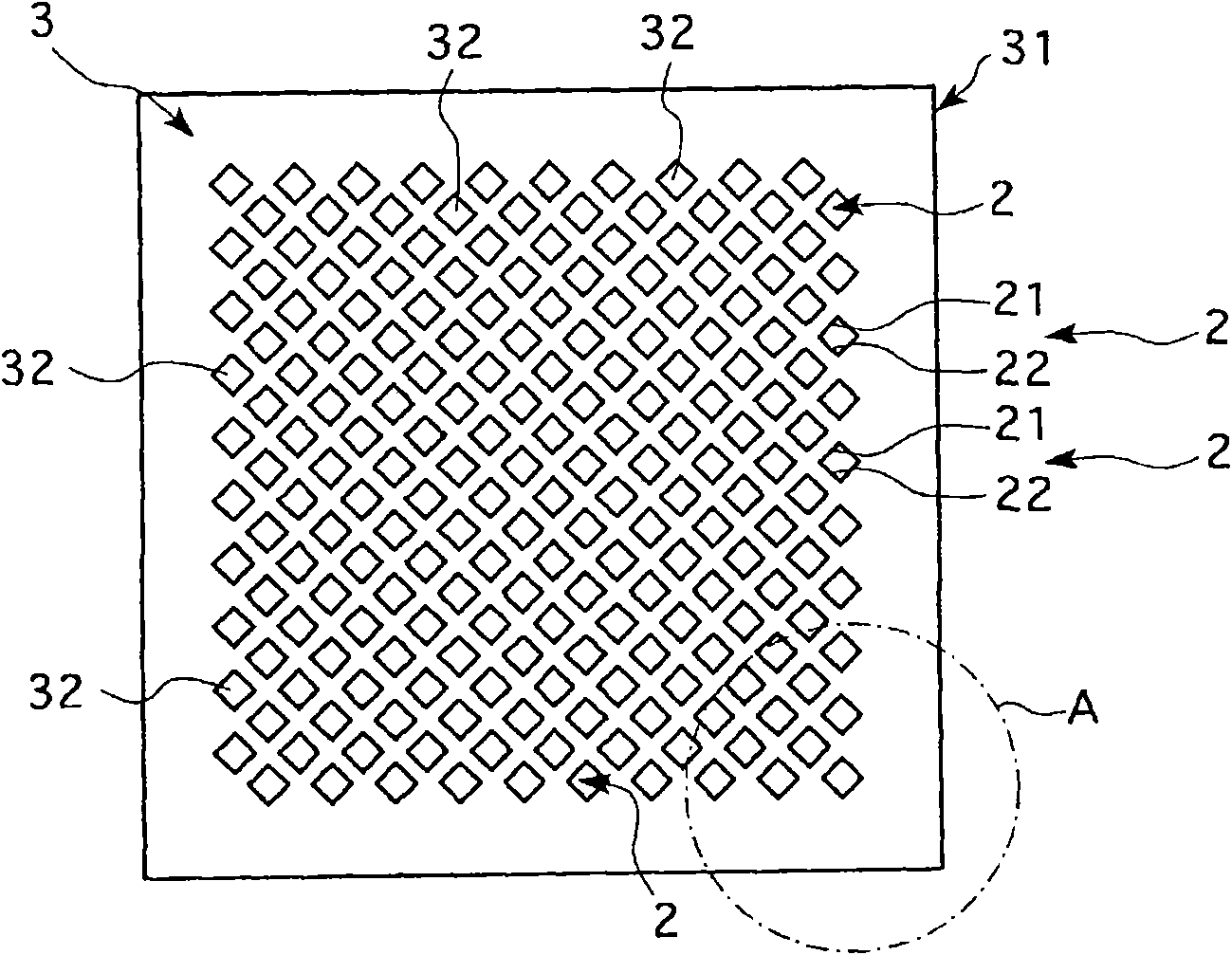
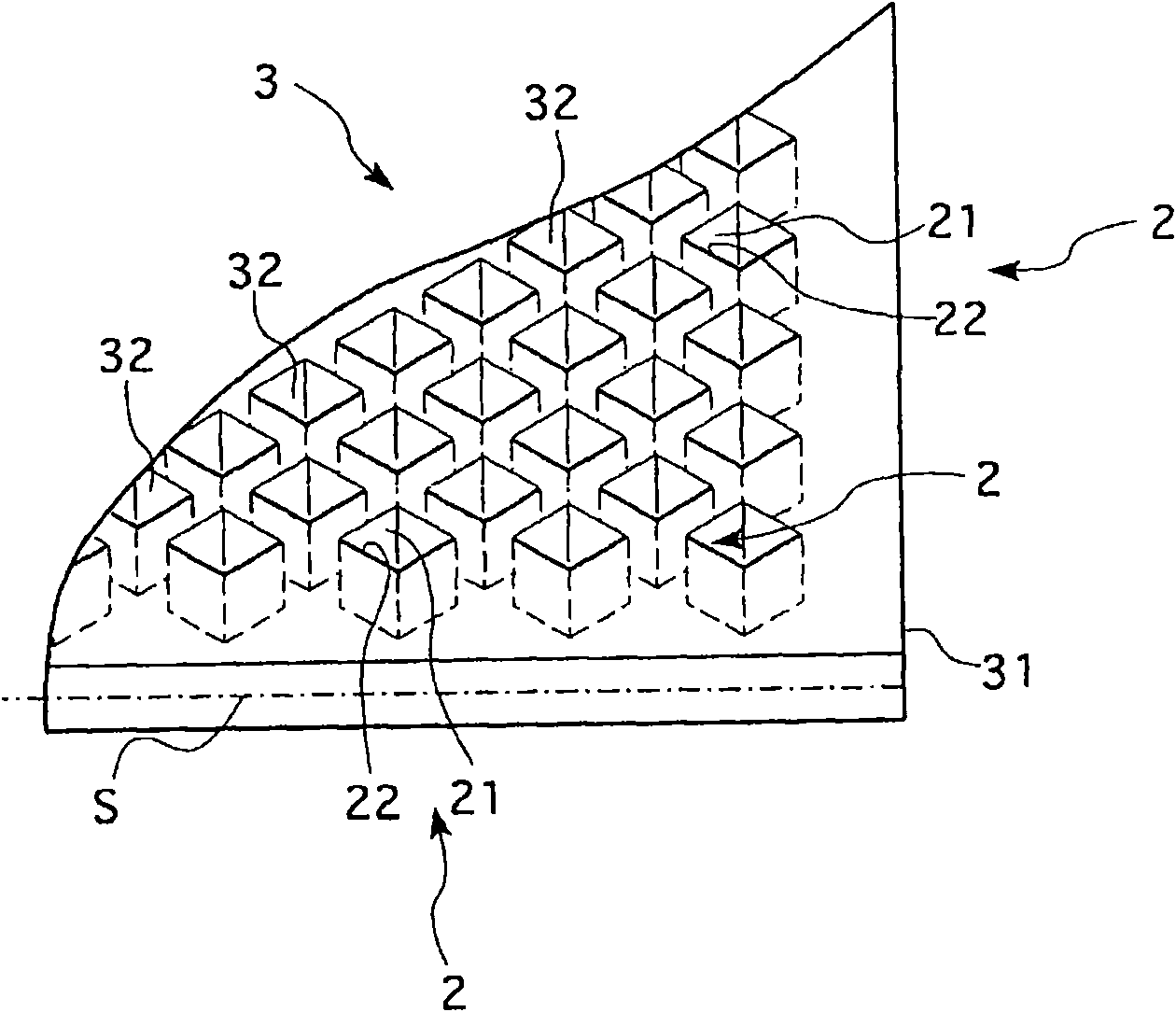
[0041] figure 1 The first embodiment shown is one of the basic forms of the transmission optical system of the present invention. That is, the transmission optical system 1A of the present embodiment uses two (reference numerals 3-1, 3-2) real-mirror image imaging optical systems (hereinafter referred to as "double-sided corner reflectors") equipped with a plurality of double-sided corner reflectors 2. reflector array") 3 to form a real image P2 having the same depth form (concave-convex) as the projected object O. The two double-sided corner reflector arrays 3-1, 3-2 are substantially identical. As shown in the figure, in this transmission optical system 1A, two double-sided corner reflector arrays 3 are arranged such that their element faces S, S are parallel to each other. In addition, since the double-sided corner reflector 2 is very small compared with the double-sided corner reflector array 3, in this figure, the entire collection of the double-sided corner reflectors ...

no. 2 approach

[0052] exist Figure 8 In the transmission optical system 1C of the second embodiment of the present invention shown as a side view in FIG. The element faces S, S of the double-sided corner reflector array 3 are not parallel to each other. Specifically, in the transmission optical system 1C of the illustrated example, four double-sided corner reflector arrays 3-1, 3-2, 3-3, and 3-4 are arranged sequentially away from the projected object O side, The first double-sided angular reflector array 3-1 and the second double-sided angular reflector array 3-2, the second double-sided angular reflector array 3-2 and the third double-sided angular reflector array 3-3, the third The double-sided corner reflector array 3 - 3 and the fourth double-sided corner reflector array 3 - 4 are respectively arranged with the element surfaces S and S inclined to each other. In addition, the imaging method in each double-sided corner reflector array 3 is the same as that described in the first embod...

no. 3 approach

[0060] exist Figure 10 In the transmission optical system 1D shown as a side view in , as an imaging optical system, two (reference numerals 4-1, 4-2) equipped with a half mirror 41 and a retroreflective element (hereinafter referred to as " The real mirror image imaging optical system 4 of the retroreflector array ") 42, thereby imaging the real image P2 having the same depth form (concave-convex) as the projected object O. In addition, the projection object O and the real image P ( P1 , P2 ) will be described using the same symbols as those in the above-described embodiments.

[0061] As the half mirror 41 , for example, a half mirror in which a thin reflective film is applied to one surface of a transparent thin plate such as transparent resin or glass can be used. In the half mirror 41, the surface that transmits and reflects light, that is, the half mirror surface S″ functions as a symmetrical plane in the transmission optical system 1D of the present embodiment. The a...


PUM

PropertyMeasurementUnit
Thickness dimensionaaaaaaaaaa

Abstract

A transmission optical system includes a plurality of image forming optical systems arranged apart from one another. Each of the image forming optical systems causes bending of light rays when the light passes through symmetric planes constituting one flat plane and reverses the appearing order of the light rays with respect to the symmetric planes when forming an image. An image of a projected object arranged on one of the symmetric planes can be formed as a real image on the other of the symmetric planes. The image forming optical system nearest from the projected object forms an image of the projected object by passing through the symmetric planes for projection while the other image forming optical systems form on the other of the symmetric planes for projection, an image of the imageformed and projected by the image forming optical system adjacent to the projected object side. Thus, the image of the projected object successively passes through the image forming optical systems for image formation, so that a 3-dimensional object and a 2-dimensional image are transferred to positions spatially apart from each other so as to form a 3-dimensional image and a 2-dimensional image,respectively, which can be observed.

Description

technical field [0001] The present invention relates to a transmission optical system that can transmit a projected object to other places for imaging through an imaging optical system, and can cause a three-dimensional object or a three-dimensional image to be inverted in the depth direction, or can be imaged as a real image without inversion. Background technique [0002] As an optical system that utilizes a conventional imaging optical system (such as a convex lens) to project an image of an object, and then transmits the image to other distant places for imaging, for example, a relay lens system can be cited as a representative example (for example, refer to the non-patent literature 1). In a relay lens system, generally, a plurality of lenses are arranged in addition to an objective lens facing an object to be projected (object to be projected), and the image of the object to be projected is imaged multiple times, so that it can be separated from the object to be projec...

Claims


Application Information

Patent Timeline
IPC IPC(8): G02B27/22G02B27/18G02B17/06G02B30/00
CPCG02B27/22G02B23/243G02B5/124G02B30/00
Inventor 前川聪
Owner NAT INST OF INFORMATION & COMM TECH
Learn More