Equipment used on spinning room preparation machines

A technology for preparing machines and equipment, which is applied to spinning machines, drafting equipment, and mechanical devices, etc. It can solve the problems of large space, disadvantages, and costs, and achieve the effects of simplifying adjustment procedures, saving space, and simplifying structure and installation.

Active Publication Date: 2014-10-22
TRUETZSCHLER GRP SE
View PDF1 Cites 0 Cited by
  • Summary
  • Abstract
  • Description
  • Claims
  • Application Information

AI Technical Summary

Problems solved by technology

One disadvantage is that it requires a considerable amount of space where space is constrained
Furthermore, the arrangement for mounting the displacement sensor, ie the outlay for the mounting, is disadvantageous

Method used


Image

  • Equipment used on spinning room preparation machines
  • Equipment used on spinning room preparation machines
  • Equipment used on spinning room preparation machines

Examples


Embodiment Construction

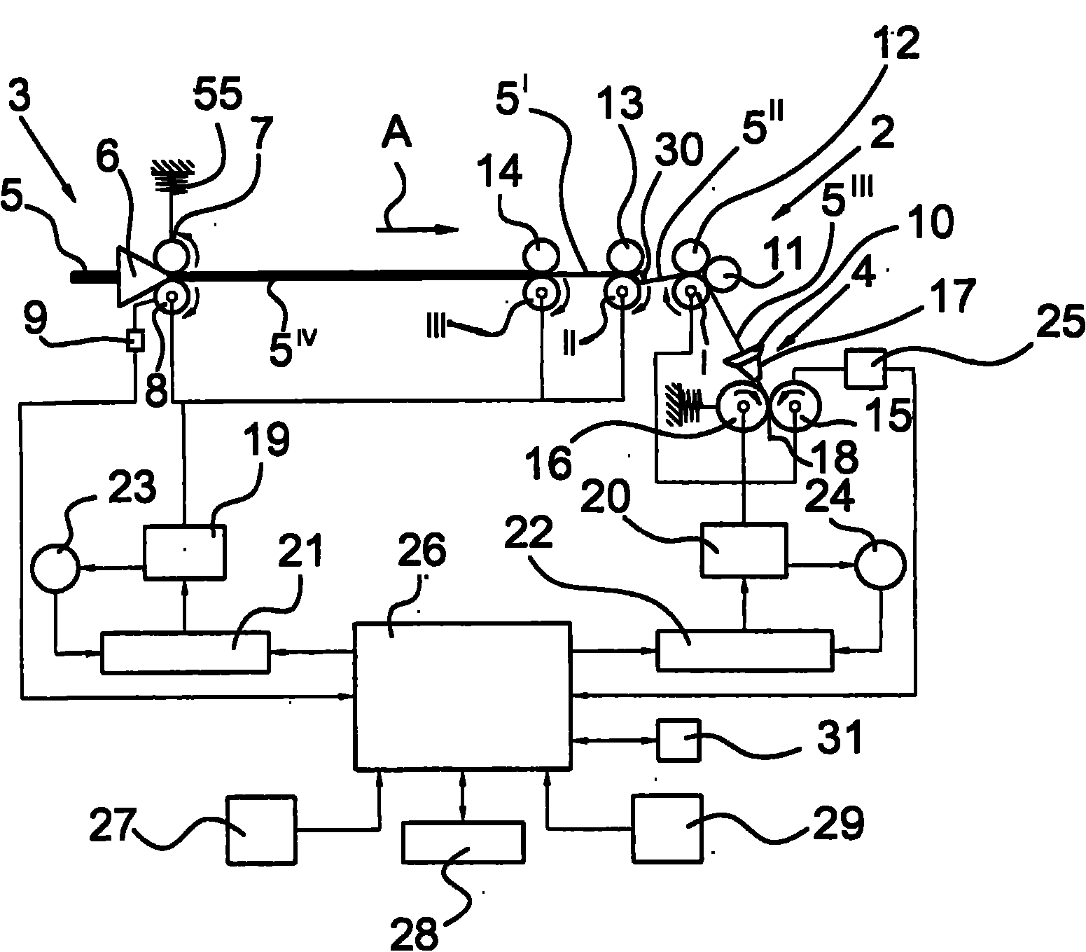
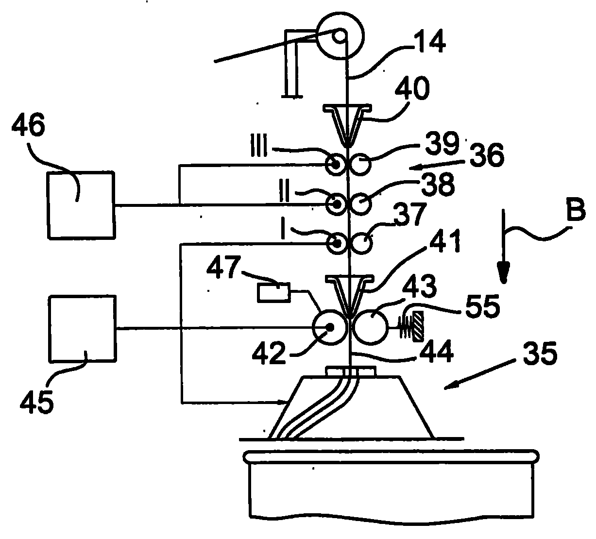
[0015] Such as figure 1 As shown, a draw frame 1 , for example of the Trützschler TD03 type, has a drafting mechanism 2 , upstream of which is an inlet 3 and downstream of which an outlet 4 . The sliver 5 from the can (not shown) enters the sliver guide 6 and is transported past the measuring element (distance sensor 9 ) drawn by the take-off rollers 7 , 8 . The drafting mechanism 2 is designed as a 4-up and 3-down drafting mechanism. That is, it includes three bottom rollers I, II, III (output bottom roller I, intermediate bottom roller II, input bottom roller III) and four top rollers 11, 12, 13, 14. Fiber strips are drawn from a plurality of fiber strips 5 and combined body 5 IV It is carried out in the drafting mechanism 2. The drafting process includes pre-drafting and main drafting. The roller pairs 14 / III and 13 / II form the pre-drafting zone and the roller pairs 13 / II and 11, 12 / I form the main drafting zone. Fiber strip merged body 5 I Drawing in the pre-drawing ...


PUM


Abstract

A spinning room preparation machine has a pair of rolls 15a, 16a pressed against one another, one of which 15a rotates about an immovable axis and one of which 16a rotates about a movable axis, a non-contact spacing sensor 57 for measuring the spacing between the rolls being associated with the holding element 52, 53 of one of the holding elements, preferably the immovable roll 15a, the sensed or counterpart surface being associated with the other holding element. The holding element 52, 53 may be a rotary bearing which may be Aluminium (Al) and may be a spring loaded movable bearing. The sensor 57 may be an inductive proximity or displacement sensor, acoustic e.g. ultrasound sensor, a plunger coil and core, a laser sensor or an optical sensor using visible or infra-red (IR) light. The sensor may sense a surface of the other housing 53, or a counterpart element integrated in the other housing (figure 6). The machine may be a carding machine, draw frame, combing machine or flyer. The spacing sensor 57 may be separable from the housing. This allows simple replacement of parts and space to be saved.

Description

technical field [0001] The invention relates to a device for use on a spinning room preparation machine, in particular a card, draw frame, comber or roving frame, which has a drafting mechanism for drawing strand-like fiber material, the device for Continuously recording the cross-sectional area and / or fiber quantity of at least one fiber strip, the device has a pair of measuring rollers arranged to press against each other, wherein one roller is arranged to be immovable and the other roller is arranged to be movable from the Said one roller is moved away, the device has a non-contact distance sensor for measuring the distance from the corresponding surface (sensed surface) associated with the holding element for one roller. Background technique [0002] It is common practice in production to measure the thickness of the fiber sliver, in particular for the purpose of leveling out the inhomogeneity of one or more fiber slivers introduced into the spinning room preparation mac...

Claims


Application Information

Patent Timeline
Patent Type & Authority Patents(China)
IPC IPC(8): D01G31/00D01G23/06D01G15/64D01G19/14D01H13/32D01H13/14D01H5/38
CPCG01B11/06D01G23/06G01B11/026D01H5/38G01B5/068
Inventor F-J·明特J·博斯曼
Owner TRUETZSCHLER GRP SE
Why Eureka
Try Eureka