Evaporator

An evaporator and the same technology, applied in the field of micro-tube evaporators, can solve the problems of mass flow distribution micro-tube evaporator performance degradation, uneven mass flow distribution of water chamber, high air side pressure drop, etc., to achieve uniform refrigerant distribution, Uniform flow and temperature distribution, easy installation and fixation

Active Publication Date: 2011-07-06
空调国际(上海)有限公司
View PDF0 Cites 0 Cited by
  • Summary
  • Abstract
  • Description
  • Claims
  • Application Information

AI Technical Summary

Problems solved by technology

However, due to the gravity of the existing evaporator, the introduced two-phase flow will produce stratification, and because the microtube protrudes into the flow channel, the resistance of the flow from the inlet to the far end will increase, and at the same time, the fluid will continue to flow into the microtube along the way. The flow tends to decrease gradually along the water chamber, so the mass flow distribution in the water chamber is uneven
Inhomogeneity of mass flow distribution in the water chamber is the main reason for the performance degradation of the microtube evaporator
To solve this technical problem, add a refrigerant distribution device in the water chamber to make the refrigerant evenly distributed along the longitudinal direction of the water chamber; or add several partitions in the water chamber to form multiple flow channels, thus dividing the water chamber into several An independently closed water chamber section, because the length of the water chamber section and the number of microtubes in a single flow channel is only a part of the entire water chamber and the number of tubes, the unevenness of the flow can be significantly improved by adding flow channels , but this design makes the performance of the evaporator poor under the same core thickness, and in order to reduce the pressure drop loss, the microtube needs to be thicker and wider. At the same time, because the size of the core and the microtube is relatively large, the air Higher lateral pressure drop

Method used


Image

  • Evaporator
  • Evaporator
  • Evaporator

Examples


Embodiment 1

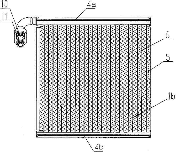
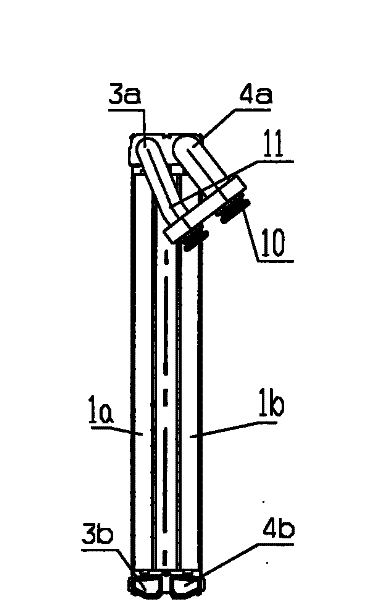
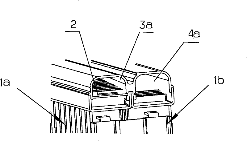
[0040] Embodiment 1: as figure 1 and figure 2 As shown, an evaporator includes: an inlet-side heat exchange tube group 1a and an outlet-side heat exchange tube group 1b composed of heat exchange tubes 5 arranged in parallel at a certain interval; and the inlet-side heat exchange tube group 1a and The outlet-side heat exchange tube group 1b is a vertical water chamber, the water chamber includes an inlet-side upper water chamber arranged at both ends of the inlet-side heat exchange tube group 1a and communicating with the inlet-side heat exchange tube group 1a Chamber 3a and inlet-side lower water chamber 3b, outlet-side upper water chamber 4a and outlet-side lower water chamber 4b arranged at both ends of the outlet-side heat exchange tube group 1b and communicated with the outlet-side heat exchange tube group 1b, the The inlet-side lower water chamber 3b and the outlet-side lower water chamber 4b communicate with each other; the inlet-side upper water chamber 3a communicate...

Embodiment 2

[0044] Embodiment 2: as figure 1 and figure 2 As shown, an evaporator includes: an inlet-side heat exchange tube group 1a and an outlet-side heat exchange tube group 1b composed of heat exchange tubes 5 arranged in parallel at a certain interval; and the inlet-side heat exchange tube group 1a and The outlet-side heat exchange tube group 1b is a vertical water chamber, the water chamber includes an inlet-side upper water chamber arranged at both ends of the inlet-side heat exchange tube group 1a and communicating with the inlet-side heat exchange tube group 1a Chamber 3a and inlet-side lower water chamber 3b, outlet-side upper water chamber 4a and outlet-side lower water chamber 4b arranged at both ends of the outlet-side heat exchange tube group 1b and communicated with the outlet-side heat exchange tube group 1b, the The inlet-side lower water chamber 3b and the outlet-side lower water chamber 4b communicate with each other; the inlet-side upper water chamber 3a communicate...

Embodiment 3

[0047] Embodiment 3: as Figure 17 As shown, the difference between this embodiment and Embodiment 1 is that the inlet-side lower water chamber 3b and the outlet-side lower water chamber 4b are also inserted and fixed with splitter plates 2b and 2c, and the splitter plates 2b and 2c divide the inlet-side lower water The chamber 3b and the outlet-side water chamber 4b are divided into upper and lower parts; the distribution plates 2b and 2c are provided with distribution holes 7b and 7c; the distribution plates 2b and 2c are also provided with installation holes, heat exchange tubes 5 Welded in the mounting hole, the ends of which protrude from the manifolds 2b and 2c, and the protruding height is preferably 1 mm to 5 mm; the specific shapes of the manifolds 2b and 2c can be as follows Figure 6 to Figure 9 shown. Other structures of this embodiment are the same as those of Embodiment 1.

[0048] When the evaporator of this embodiment is in operation, part of the liquid refri...


PUM


Abstract

The invention relates to an evaporator, which comprises a heat exchanger pipe group on an entrance side, a heat exchanger pipe group on an exit side and a water chamber. The water chamber comprises an upper water chamber (4a) on the exit side and a lower water chamber (4b) on the exit side, wherein the upper water chamber (4a) and the lower water chamber (4b) are arranged at two ends of the heat exchanger pipe group on the exit side and communicated with the heat exchanger pipe group (1b) on the exit side; a lower water chamber (3b) on the entrance side is communicated with the lower water chamber (4b) on the exit side; an upper water chamber (3a) on the entrance side is communicated with a liquid inlet pipe (10); the upper water chamber (4a) on the exit side is communicated with a liquidoutlet pipe (11); and fins (6) are welded between the heat exchanger pipes. The key point of the evaporator lies in that flow distributing devices capable of uniformly distributing refrigerant mass flow rate are arranged in the water chambers. Because a liquid refrigerant is uniform in the evaporator, the evaporator has a good refrigerating effect. The evaporator has the advantages of convenient manufacturing and assembling and small volume.

Description

technical field [0001] The invention relates to an evaporator used for an air conditioner, in particular to a microtube evaporator applied to an automobile air conditioner. Background technique [0002] Extruded porous microtubes are widely used in compact heat exchangers such as automotive evaporators and condensers. Microtube evaporators, as the main challenger of cascading evaporator technology, have become mainstream in automotive industry applications . However, due to the gravity of the existing evaporator, the introduced two-phase flow will produce stratification, and because the microtube protrudes into the flow channel, the resistance of the flow from the inlet to the far end will increase, and at the same time, the fluid will continue to flow into the microtube along the way. The flow tends to decrease gradually along the water chamber, thus resulting in an uneven mass flow distribution in the water chamber. The inhomogeneity of the mass flow distribution in the ...

Claims


Application Information

Patent Timeline
Patent Type & Authority Patents(China)
IPC IPC(8): F25B39/02
Inventor 曾欣叶粮
Owner 空调国际(上海)有限公司
Why Eureka
Try Eureka