Cooling system of a superconducting machine

A technology of superconducting motors and cooling systems, applied in the usage of superconductor elements, cooling/ventilation devices, electrical components, etc., can solve the problems of weak cooling cycle and no longer able to guarantee the cooling of windings, and achieve the effect of preventing bending loads

Inactive Publication Date: 2013-02-06
SIEMENS AG
View PDF3 Cites 0 Cited by
  • Summary
  • Abstract
  • Description
  • Claims
  • Application Information

AI Technical Summary

Problems solved by technology

If a motor installation with such a cooling circuit is now used on a ship or an offshore platform, the gravity-operated cooling circuit may not work effectively, so that reliable winding cooling can no longer be guaranteed

Method used


Image

  • Cooling system of a superconducting machine
  • Cooling system of a superconducting machine

Examples


Embodiment Construction

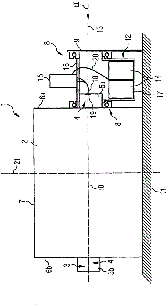
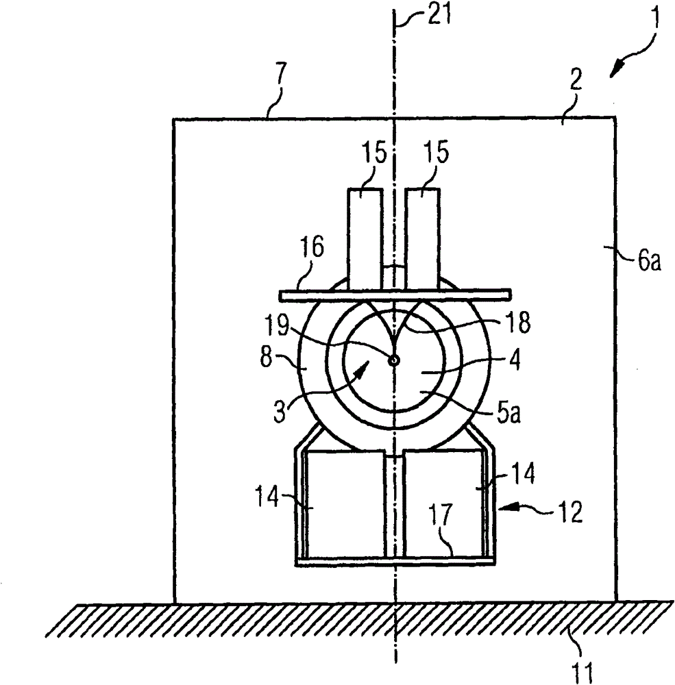
[0012] The electrical machine arrangement 1 shown in the figure has an electrical machine 2 and a cooling system. The electric machine is, for example, a synchronous electric motor or a generator, comprising a rotor 3 with a superconducting winding, in the figure only the rotor shaft 4 and its terminal section 5a protruding from the end walls 6a, 6b of the machine housing 7 , 5b is visible. The basic construction of electric machines with superconducting windings is known from the documents mentioned at the outset, to which reference is expressly made here. Arranged on the end wall 6 a is a circular link body 8 , wherein the link body is formed, for example, by a ball bearing or a roller bearing. A further link body 8 is fastened to a bracket 9 positioned at a distance from the end wall 6a, wherein this link body can likewise be designed as a rolling or ball bearing. The link body 8 is arranged coaxially to the axis of rotation 10 of the rotor 3 and serves to support a carri...


PUM


Abstract

A superconducting machine device is disclosed including a machine; a rotor including a superconductive coil; and a cooling system including at least one incline-intolerant component for cooling the coil. In at least one embodiment, at least one component is held by a carrier compensating for an incline of the machine device.

Description

technical field [0001] The invention relates to an electric machine comprising an electric machine with a superconducting rotor winding and a cooling system for cooling the rotor winding or the rotor. Background technique [0002] Cooling systems of such devices as are known, for example, from DE 100 57 664 A1, DE 103 21 463 A1 and DE 100 39 964 A1 usually have parts that do not allow tilting, which is problematic when used on ships or offshore platforms. For oil-lubricated compressors, for example, it is necessary that the suction area of ​​the lubrication circuit is always arranged inside the oil sump or oil pan. In extreme inclination situations there is therefore sometimes a fear of an interruption of the lubrication with the resulting negative consequences. Furthermore, there is a risk that the compressed working gas will become contaminated with oil, since oil separators and adsorbers are designed for vertical operation. Superconducting windings are mostly cooled by ...

Claims


Application Information

Patent Timeline
Patent Type & Authority Patents(China)
IPC IPC(8): H02K9/24H02K55/04
CPCH02K55/04H02K9/24Y02E40/60
Inventor M·弗兰克P·范哈塞尔特
Owner SIEMENS AG
Why Eureka
Try Eureka