Rotatable castor mechanism for household

A technology of rotating feet and casters, applied in the directions of casters, wheels, transportation and packaging, etc., can solve the problems of multi-purpose use and inability to turn up and down in the home, and achieve the effect of convenient positioning, reasonable structure and excellent working performance.

Inactive Publication Date: 2010-03-03
徐李华
View PDF0 Cites 4 Cited by
  • Summary
  • Abstract
  • Description
  • Claims
  • Application Information

AI Technical Summary

Problems solved by technology

[0002] Existing household casters for cribs and the like generally cannot be turned up and down, making it impossible for multi-purpose use in household

Method used


Image

  • Rotatable castor mechanism for household
  • Rotatable castor mechanism for household

Examples


Embodiment Construction

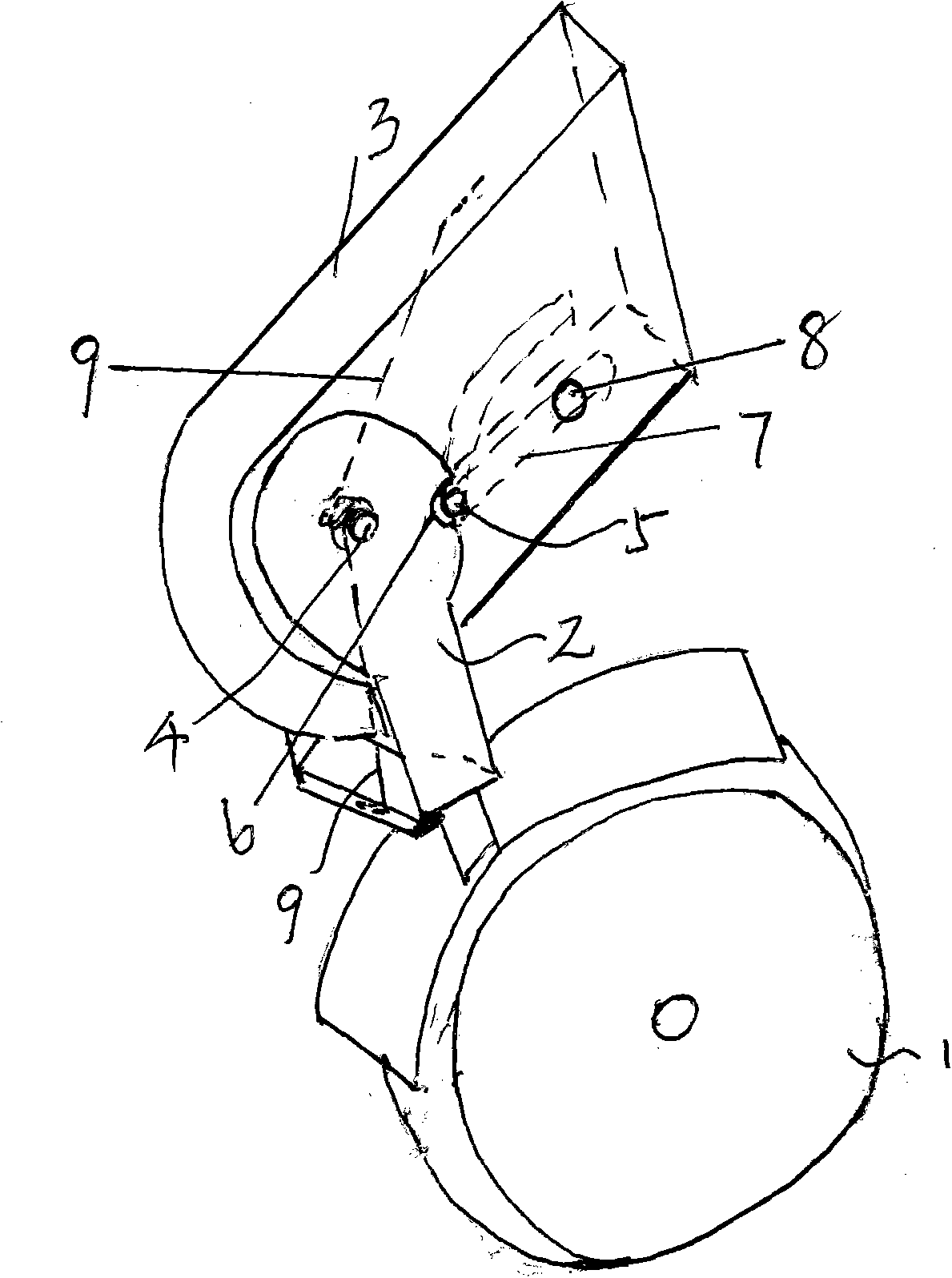
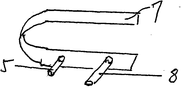
[0012] A household rotatable caster mechanism, including a caster 1, the caster is connected to a rotating connecting arm 2 that can rotate up and down, and the rotatable connecting arm is rotatably connected to a home rail connecting piece 3 through a pin shaft 4, and the home rail connecting piece is rotatably connected. A telescopic card protrusion 5 is provided, and a positioning card slot 6 cooperating with the telescopic card protrusion is provided on the rotatable connecting arm. The telescoping snap is connected with the reed 7 installed in the household cross bar connector, and the reed 7 is connected with the button 8 controlling the action of the reed.

[0013] The torsion spring 9 that drives the rotatable connecting arm to turn upwards is adorned in the household horizontal bar connector.


PUM


Abstract

The invention discloses a rotatable castor mechanism for household, comprising a castor connected with a rotatable connection arm that can rotate up and down; the rotatable connection arm is rotatablyconnected with a household cross rod connecting piece via a pin shaft; a telescopic bump is arranged on the household cross rod connecting piece; and a positioning trough matched with the telescopicbump is arranged on the rotatable connection arm. The invention has reasonable structure and excellent working performance, and is very convenient in turning upside down and positioning.

Description

Technical field: [0001] The invention relates to a household caster mechanism. Background technique: [0002] Existing household casters used for cribs and the like generally cannot be turned up and down, causing the household to be unable to be used for multiple purposes. Invention content: [0003] The object of the present invention is to provide a household rotatable caster mechanism with reasonable structure, convenient turning over and good working performance. [0004] Technical solution of the present invention is: [0005] A rotatable caster mechanism for home use, characterized in that it includes casters, the caster is connected with a rotatable connecting arm that can rotate up and down, the rotatable connecting arm is rotatably connected with the connecting piece of the horizontal bar of the home through a pin shaft, and the connecting piece of the horizontal bar of the home is rotatably connected. A telescopic card protrusion is provided, and a positioning ...

Claims


Application Information

Patent Timeline
Patent Type & Authority Applications(China)
IPC IPC(8): B60B33/02
Inventor 徐李华
Owner 徐李华
Why Eureka
Try Eureka