Image forming apparatus and image forming unit

一种图像、涂布装置的技术,应用在应用电荷图形的电记录工艺、应用电荷图形的电记录工艺的设备、电记录术等方向,能够解决调色剂不稳定等问题,达到防止图像不良的效果

Inactive Publication Date: 2010-03-03
KYOCERA DOCUMENT SOLUTIONS INC
View PDF1 Cites 5 Cited by
  • Summary
  • Abstract
  • Description
  • Claims
  • Application Information

AI Technical Summary

Problems solved by technology

Therefore, supply of toner from the developing roller to the peripheral surface of the photosensitive drum becomes unstable, resulting in failure to form a stable toner image on the peripheral surface of the photosensitive drum.

Method used


Image

  • Image forming apparatus and image forming unit
  • Image forming apparatus and image forming unit
  • Image forming apparatus and image forming unit

Examples


Embodiment Construction

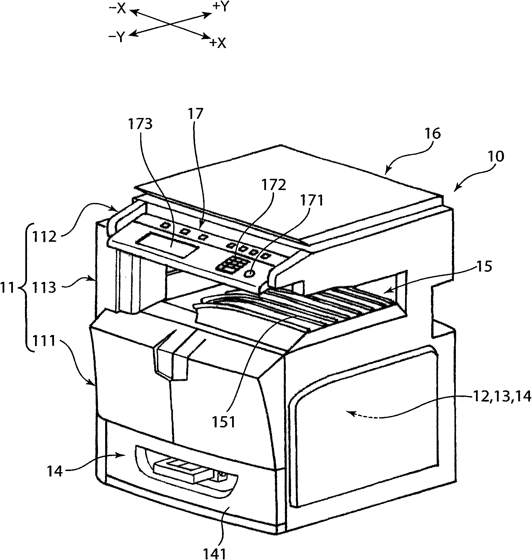
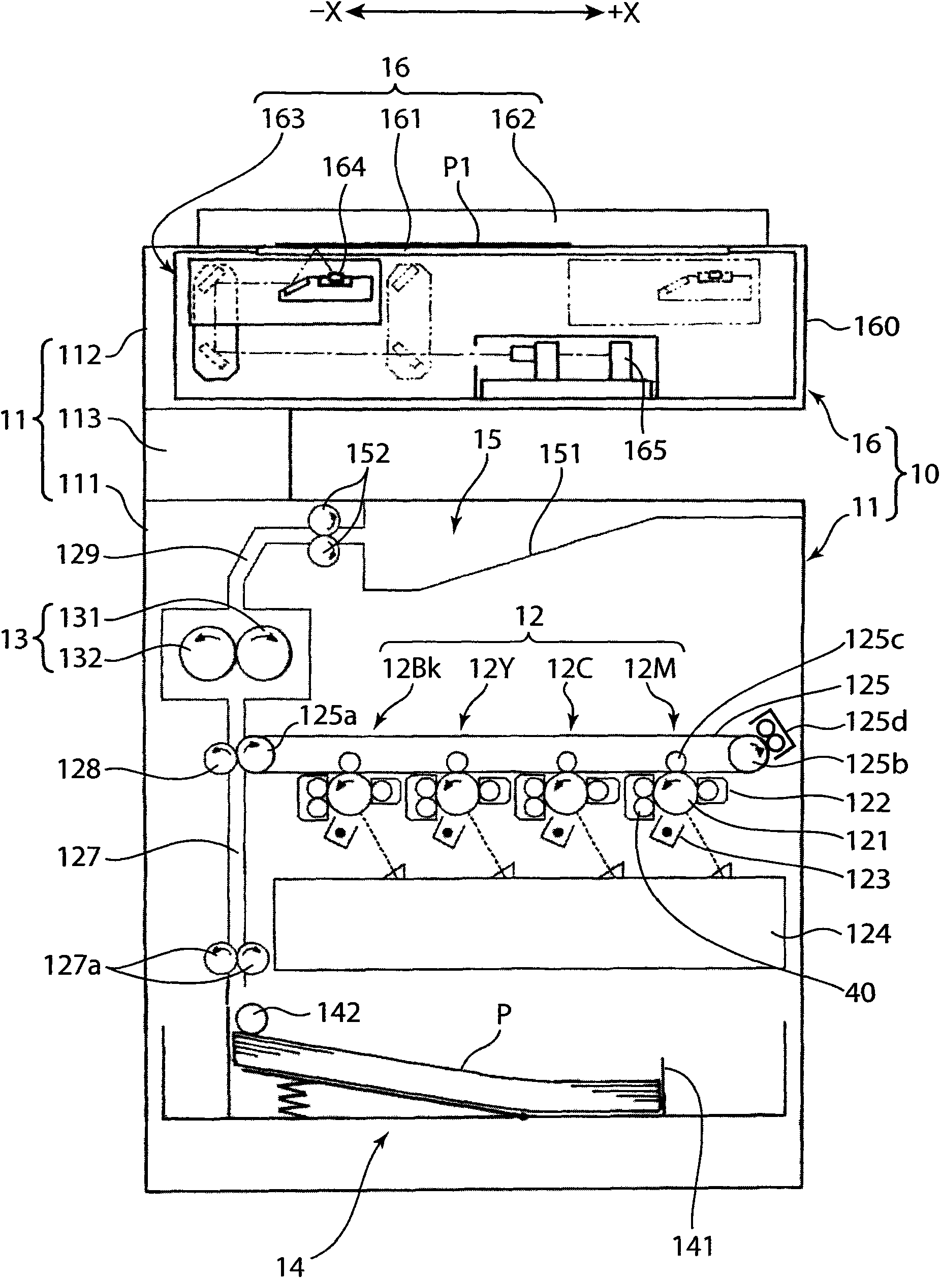
[0029] figure 1 is a perspective view showing an embodiment of the image forming apparatus 10 of the present invention, figure 2 It is a front cross-sectional view for explaining the internal structure of the image forming apparatus 10 . Moreover, in figure 1 with figure 2 Among them, the X-X direction is called the left and right direction, the Y-Y direction is called the front and rear direction, specifically the -X direction is called the left side, the +X direction is called the right side, the -Y direction is called the front, and the +Y direction is called the rear .

[0030] The image forming apparatus 10 is a copying machine of a so-called internal discharge type, and includes: an apparatus main body 11, an image forming unit 12 mounted on the apparatus main body 11, a fixing unit 13, a paper storage unit 14, a paper ejection unit 15, An image reading unit 16 and an operation unit 17 . In the lower part of the image reading section 16 , a paper discharge section...


PUM


Abstract

An image forming apparatus is provided with an image bearing member for bearing a toner image while rotating, a developing device including a developing roller for supplying toner to a surface of theimage bearing member and a pair of gap rollers held in contact with opposite end portions of the image bearing member to define a specified gap between the developing roller and the surface of the image bearing member, and a lubricant applicator for applying a lubricant to parts of the opposite end portions of the image bearing member where the gap rollers are in contact.

Description

technical field [0001] The present invention relates to an image forming apparatus having an image carrier on which a toner image is formed on the surface, and an image forming unit used in the image forming apparatus. Background technique [0002] An electrostatic latent image is formed on the peripheral surface of a photosensitive drum (image carrier) by reading an original image, or based on image information transmitted from an external computer, etc., and toner is supplied to the electrostatic latent image from a developing device, in which An image forming apparatus having a structure in which a toner image is formed on a peripheral surface and the toner image is transferred onto paper is known. [0003] In such an image forming apparatus, due to the residual toner remaining on the peripheral surface of the photosensitive drum after the transfer process on the paper, or the application of a high voltage before forming an electrostatic latent image attached to the perip...

Claims


Application Information

Patent Timeline
Patent Type & Authority Applications(China)
IPC IPC(8): G03G21/00
CPCG03G2221/1609G03G15/751G03G15/0813G03G21/16
Inventor 合田光弘福永靖幸
Owner KYOCERA DOCUMENT SOLUTIONS INC
Why Eureka
Try Eureka