
Cab frame for construction machinery and painting method therefor

Active Publication Date: 2014-12-04
KOMATSU LTD
View PDF0 Cites 4 Cited by
  • Summary
  • Abstract
  • Description
  • Claims
  • Application Information

AI Technical Summary

Benefits of technology

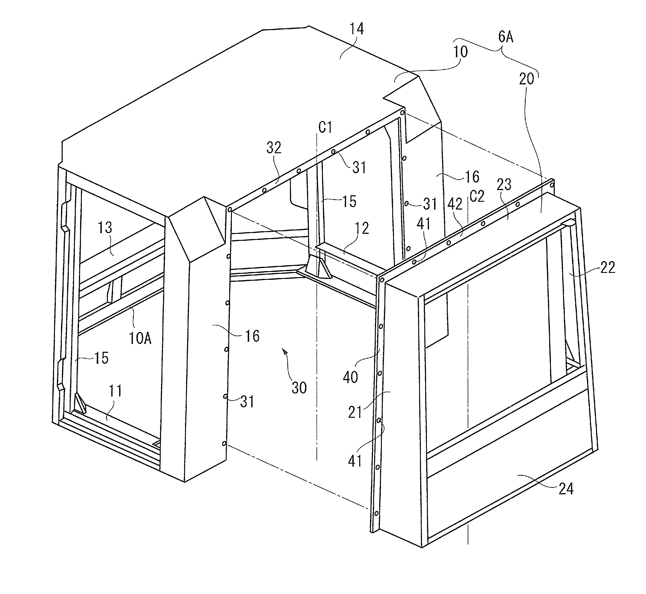
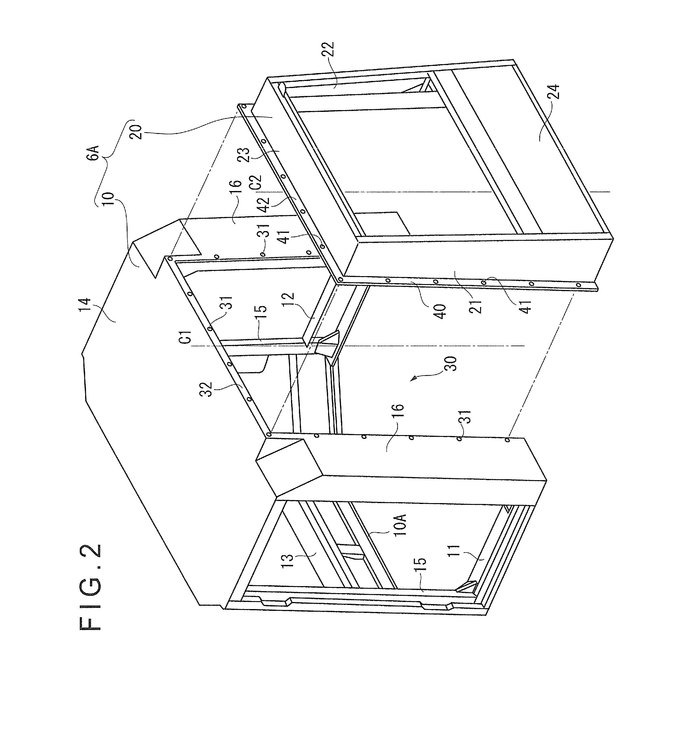
The invention describes a new way to coat cab frames to increase rigidity and protect the frame from damage. By dividing the frame into a main structure and a substructure that can be connected to the main structure in an inverse connection direction, the substructure does not stick out and can be easily immersed in the coating bath. The use of ROPS frame also protects the connectors between the main and substructures. This technique makes the cab frame more durable and easier to handle.

Problems solved by technology

When the technique as suggested by Patent Literature 1 is applied to coating, two divided frame parts are separately immersed in an electrodeposition bath, which results in increasing a man-hour for coating and thus in unintentionally lowering productivity.

Method used


Image

  • Cab frame for construction machinery and painting method therefor
  • Cab frame for construction machinery and painting method therefor
  • Cab frame for construction machinery and painting method therefor

Examples


Embodiment Construction

)

[0026]Exemplary embodiment(s) of the invention will be described below with reference to the attached drawings.

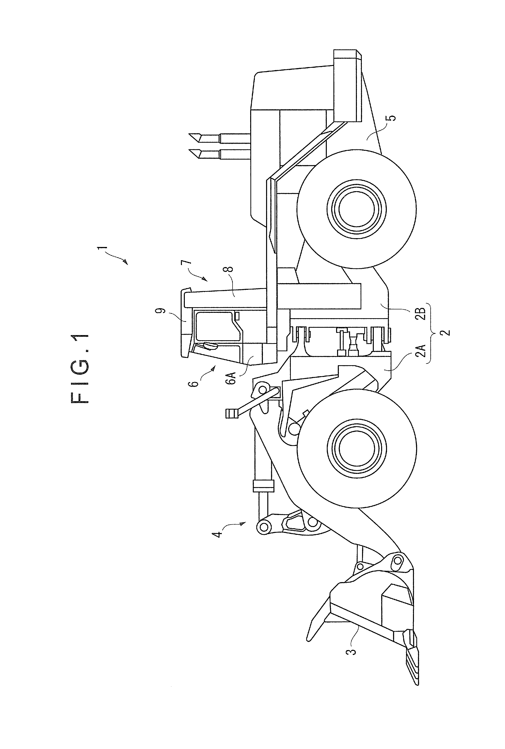
[0027]FIG. 1 is a side view showing a large-sized wheel loader 1 as a construction machine according to an exemplary embodiment. It should be noted that front / rear and right / left hereinafter mean front / rear and right / left defined when an operator is seated in a cab 6 as shown in FIG. 1.

[0028]As shown in FIG. 1, the wheel loader 1 includes a vehicle body 2 including a front vehicle body 2A and a rear vehicle body 2B. An excavating / loading bucket 3 is attached to a front side (a left side in FIG. 1) of the front vehicle body 2A via a hydraulic working-equipment-driving mechanism 4 including a boom, a bell crank, a connecting link, a bucket cylinder and a boom cylinder.

[0029]The rear vehicle body 2B includes a rear-vehicle-body frame 5 made of a thick metal plate or the like. A front side of the rear-vehicle-body frame 5 is provided with the box-shaped cab 6 where an operator...


PUM


Abstract

A cab frame includes: a main structure having an opening on a part of an outer surface thereof; a rear structure separably connected to the main structure to cover the opening while projecting from the main structure; and first and second connectors provided to the main structure and the rear structure, respectively, the first and second connectors connected to each other in an abutted manner when the main structure and the rear structure are connected to each other. When the rear structure is connected to the main structure after being turned back to front relative to the main structure, the rear structure is temporarily fixable to the main structure via the first and second connectors. When the rear structure is turned back to front and connected to the main structure, the rear structure is housed in the main structure.

Description

TECHNICAL FIELD[0001]The present invention relates to a cab frame for a large-sized construction machine such as a wheel loader and a coating method therefor.BACKGROUND ART[0002]There is already known a construction machine including a box-shaped cab in which an operator is seated, such as a wheel loader, a bulldozer and an excavator. The cab of such a construction machine includes a cab frame built by, for instance, welding metal plates. The cab frame is independently coated before being mounted on a vehicle body and a typical coating method for the cab frame is cationic coating according to which the cab frame is immersed in an electrodeposition bath with a material for cationic electrodeposition coating.[0003]In some large-sized construction machines, a seat for a trainer is provided in the cab in addition to an operator seat. In such a case, the cab itself is also designed to be large for the necessity of increasing the space therein. Further, in order to meet a demand for, for ...

Claims


Application Information

Patent Timeline
IPC IPC(8): E02F9/16
CPCE02F9/163B62D21/186E02F9/0841C25D13/12C25D13/20C25D13/22
Inventor OHTA, NOBUYUKIOHKI, SHINJIROU
Owner KOMATSU LTD
Learn More