
Method for applying an electrical insulation

a technology of electrical insulation and electrical insulation, applied in the direction of electrostatic spraying apparatus, dynamo-electric machines, coatings, etc., can solve the problems of requiring a complicated conveyor system for feeding the armature, wasting time and money, and wasting resources

Inactive Publication Date: 2006-08-10
ROBERT BOSCH GMBH
View PDF5 Cites 4 Cited by
  • Summary
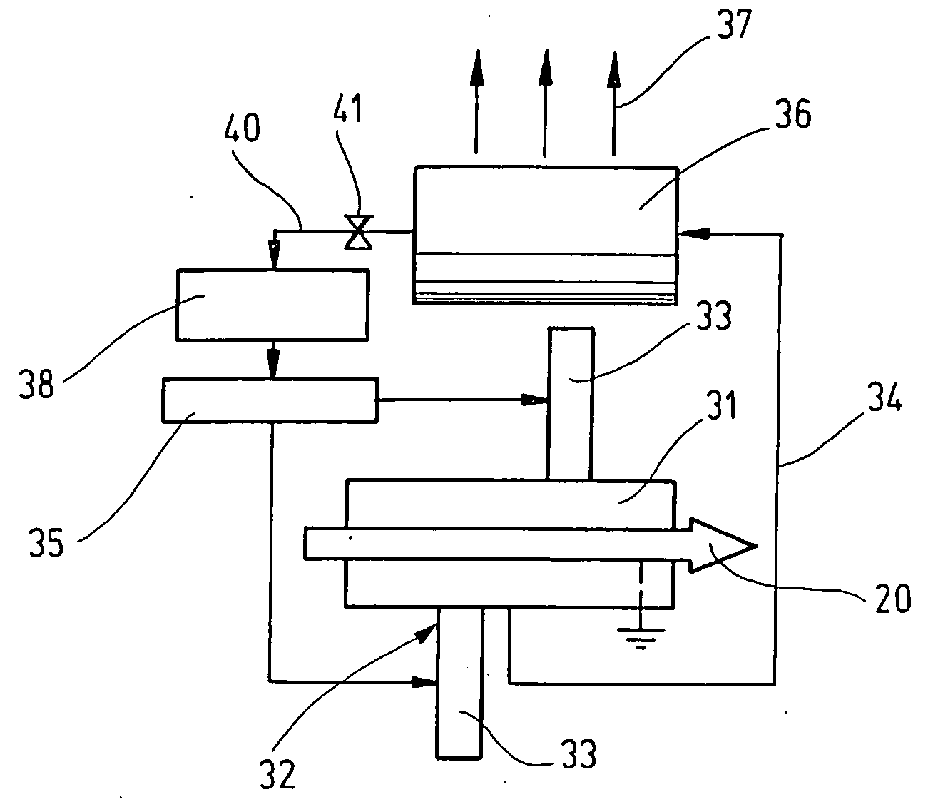
  • Abstract
  • Description
  • Claims
  • Application Information

AI Technical Summary

Benefits of technology

[0007] The method of the invention thus takes on all the advantages of electrostatic powder spray-coating for decorative surfaces and, unlike that method, also assures reliably insulated coating of the slot walls with plastic powder. The application of a high layer thickness assures that a sufficiently thick powder layer will become deposited on the slot walls; this layer is as a rule thinner than the powder layer on the cylindrical surface of the body, yet it offers reliable insulating lining of the slots. The high layer thickness applied is greater by a factor 10 to 50 than the layer thicknesses that are achieved in powder coating of decorative surfaces and is in the range of approximately 1 to 1.5 mm. In electrostatic powder spraying, the axial slots are so-called Faraday cages, which are field-free, since the field lines of the magnetic field that develops between the spray source and the preferably grounded body, along which lines the electrically charged powder particles move, are concentrated at tips and protrusions and do not penetrate into the axial slots. Because of the so-called electrostatic embrace, that is, the fact that the field lines also extend to the face ends of the armature body, powder particles, while being electrostatically deposited at the ends of the slots, are not deposited in the slot interior. By the application of what according to the invention is a high layer thickness, the deposition of powder does occur first at points with high field line concentration at the beginning of the coating process. However, as spraying continues, saturation at these points ensues. The saturated points can no longer be coated, since a charge concentration occurs there. The powder particles that continue to arrive carry the same charge and are spun away from the body by electrostatic repulsion (back-spray effect). Since the spray source is electrically identically charged, however, the particles are not speeded up backward but instead are no longer subject to any external force from the field lines and penetrate into the interior of the axial slots.
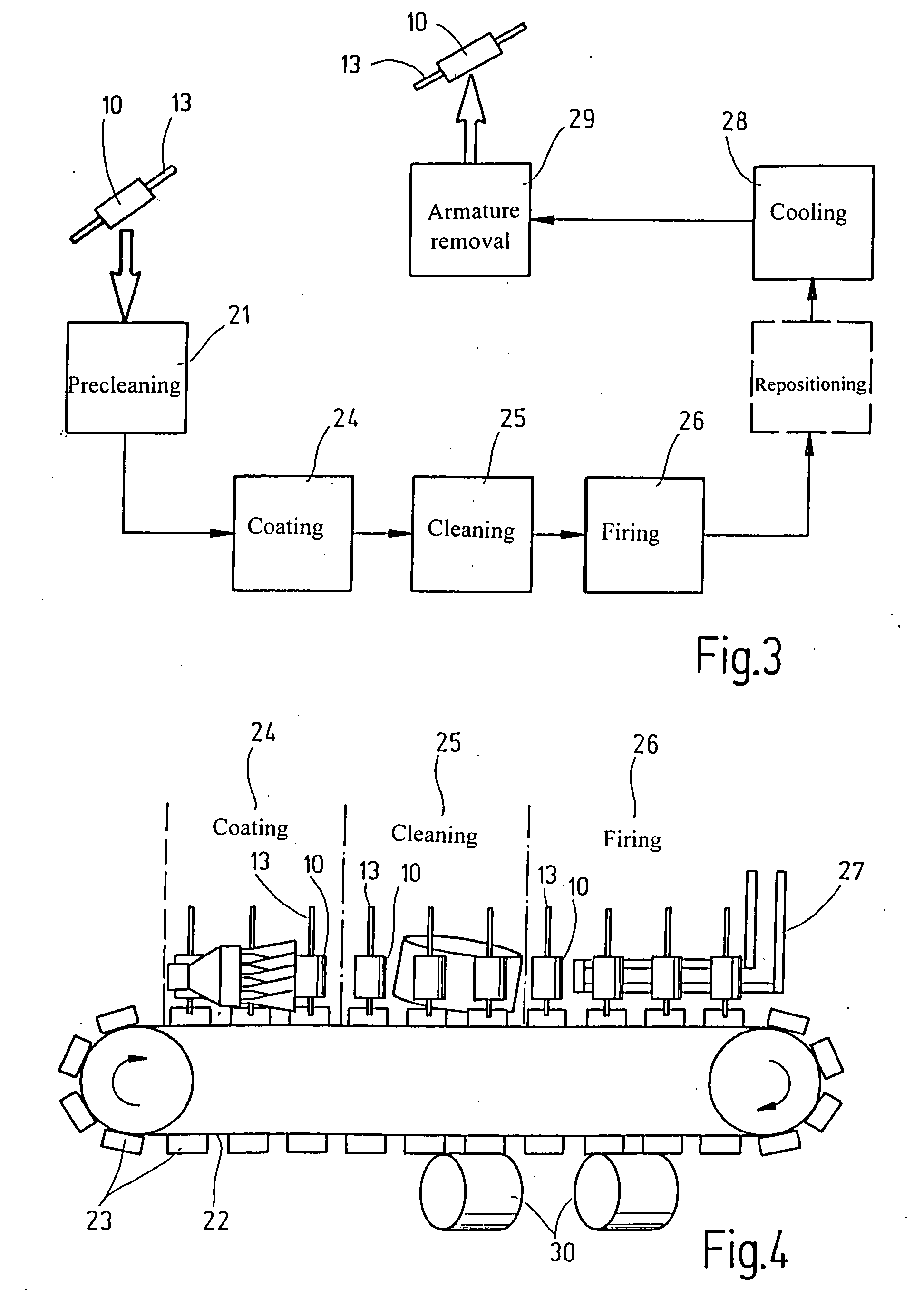
[0008] Another advantage of the method of the invention is the improvement in handling the bodies in the production process, since unlike the known method that uses a fluid bath, the bodies can be sprayed in an arbitrary position and need not necessarily be put into a horizontal position. This dispenses with repositioning of the bodies, and thus further auxiliary stations in the course of the method can be dispensed with.

Problems solved by technology

This method produces a thin insulation layer, approximately 50 to 100 μm thick, in the axial slots with good thermal and electrical properties, but has decisive disadvantages in terms of costs.
For instance, the fluid bath requires a horizontal position of the armature bodies, which in the rest of the production process are usually processed vertically, so that as the method progresses, the armature bodies have to be repositioned multiple times. Moreover, a quite complicated conveyor system is required for feeding the armature bodies through the fluid bath.
If damage occurs in the fluid bath, replacing the fluid bath that is integrated into the system is extremely time-consuming and leads to expensive system down times. The masks also take on the function of clamping the armature bodies while they are being conveyed.
If the masks become worn, inadequate clamping of the armature bodies can occur, which threatens the course of the process and leads to down times.

Method used


Image

  • Method for applying an electrical insulation
  • Method for applying an electrical insulation
  • Method for applying an electrical insulation

Examples


Embodiment Construction

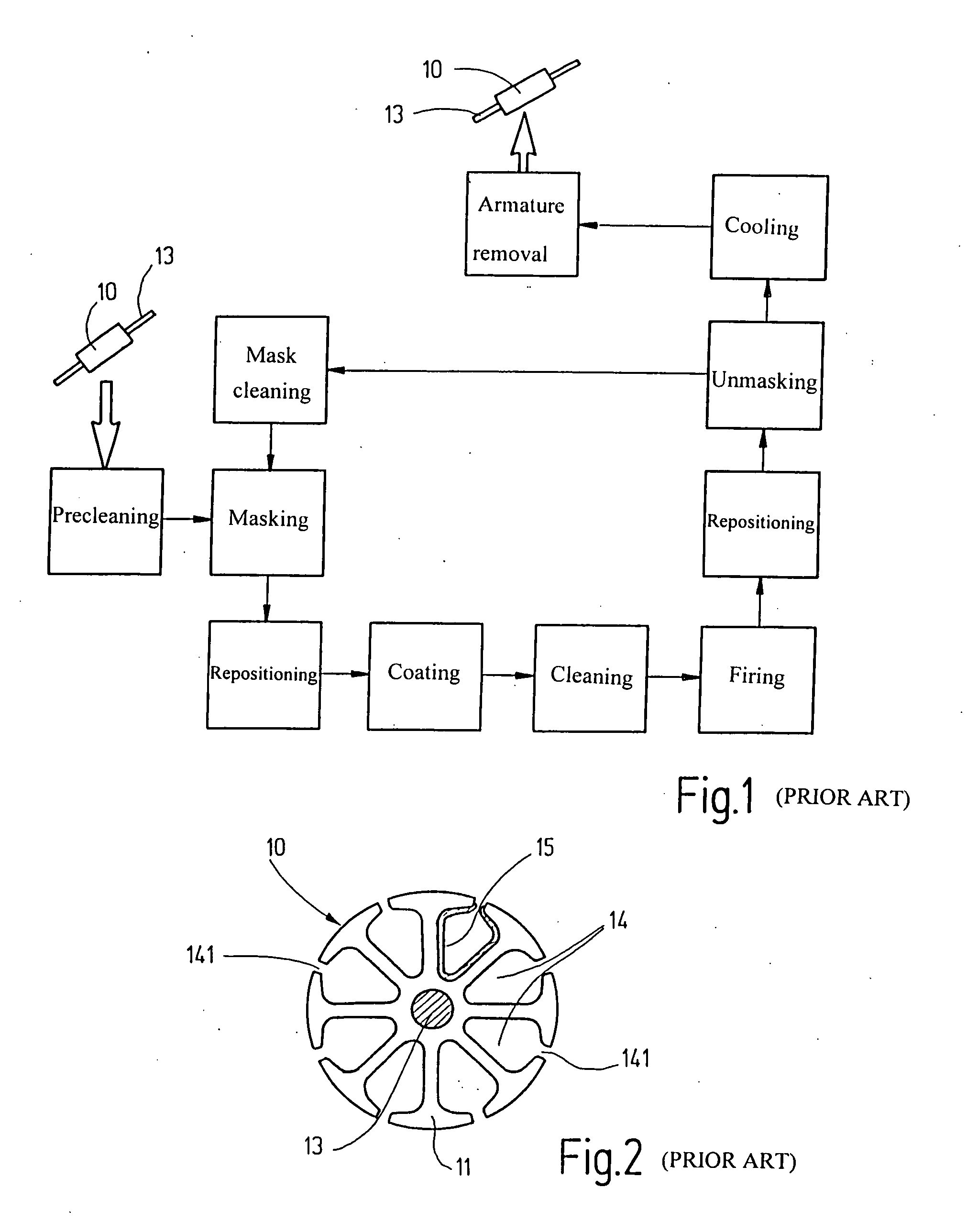
[0017] The method for applying an electrical insulation to a ferromagnetic body, provided with axial slots for receiving an electrical winding, of a primary element or in other words a stator or a rotor of an electrical machine will be described in terms of a slotted armature body 10 of an armature of a direct-current motor. The armature body 10, which can be seen end-on in FIG. 2, comprises a plurality of profiled laminations 11, which are lined up one after the other to form a so-called lamination packet and are axially joined firmly together. Instead of a profiled lamination packet, the armature body 10 may be embodied as a solid cylinder of soft magnetic composite material, or SMC (Soft Magnetic Composite) material. The armature body 10 is provided in a known manner with a plurality of axial slots 14, located equidistantly over the circumference of the body, for receiving an armature winding.

[0018] The armature bodies 10, pressed onto the armature shaft 13, are precleaned in a ...


PUM


Abstract

In a method for applying an electrical insulation to a ferromagnetic body, provided with axial slots for receiving an electrical winding, of a primary element of an electrical machine, particularly to a slotted armature body of an armature of a direct-current motor, the body is coated with electrostatically charged plastic powder. For improving the economy of the method with a view to low system costs and great ease of maintenance while assuring reliable slot insulation, the coating is done with a high layer thickness by direct powder spraying onto the grounded body.

Description

PRIOR ART [0001] The invention is based on a method for applying an electrical insulation to a ferromagnetic body, provided with axial slots for receiving an electrical winding, of a primary element of an electrical machine, in particular to a slotted armature body of an armature of a direct-current motor, as generically defined by the preamble to claim 1. [0002] A slotted armature body of an armature of a direct-current motor, of the kind shown for instance in plan view in FIG. 2, comprises a plurality of profiled laminations 11, which are lined up axially one after the other and joined to make a lamination packet. The armature body 10 is press-fitted onto an armature shaft 13. The armature body 10 has a plurality of axial slots 14, which are open to both face ends of the cylindrical armature body 10 and which discharge at a slot opening 141 in the cylindrical surface of the armature body 10. An armature winding in the form of coils is wound into the axial slots 14. The coils are w...

Claims


Application Information

Patent Timeline
IPC IPC(8): B05D1/04B05B5/025B05D1/06H02K15/12
CPCB05D1/06H02K15/12H02K3/38
Inventor HUEHSAM, ANDREAS
Owner ROBERT BOSCH GMBH
Learn More