Hammer drill

A technology of hammer drill and cylinder, applied in the field of hammer drill, can solve the problems of high cost, high manufacturing requirements, large space, etc., and achieve the effects of reduced production cost, compact structure, and low manufacturing and assembly costs

Active Publication Date: 2011-09-07
POSITEC POWER TOOLS (SUZHOU) CO LTD
View PDF2 Cites 2 Cited by
  • Summary
  • Abstract
  • Description
  • Claims
  • Application Information

AI Technical Summary

Problems solved by technology

In this kind of function switching mechanism, the sliding sleeve and the cylinder need to cooperate well, the manufacturing requirements are high, and the corresponding cost is large.
At the same time, the entire set of switching elements will undergo relative axial displacement during the operation process, the space required for the entire set of mechanisms is large, and the movement of each component during the operation process is complicated.

Method used


Image

  • Hammer drill
  • Hammer drill
  • Hammer drill

Examples


no. 1 example

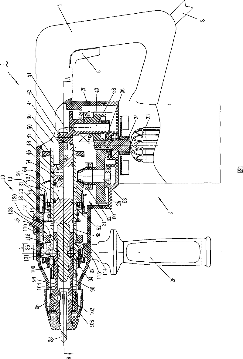
[0066] see attached below Figure 1-8 , The hammer drill 1 according to the first embodiment of the present invention includes a housing 2, a motor 33, an operating tool 28, an impact force transmission mechanism 30, a rotational force transmission mechanism 31, a switching mechanism 10, and the like. The hammer drill 1 can be operated in a rotary and percussion mode (hammer drill), percussion only mode (hammer), rotary only mode (drill) and an intermediate mode (hammer swivel).

[0067] The hammer drill 1 includes a handle 4 provided on the rear end of the housing 2, a switch 6 provided on the handle 4, a cable 8 connected to the handle 4 for supplying electric power to the hammer drill 1, rotatably provided on the housing A switch mechanism 10 on the body 2 for switching operation modes, and an auxiliary handle 26 arranged near the front end of the housing 2 . The operating tool 28 is attached to the front end of the hammer drill 1 via a chuck 96 . The operating tool 28 re...

no. 2 example

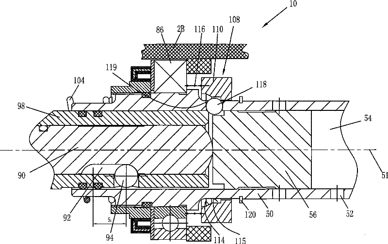
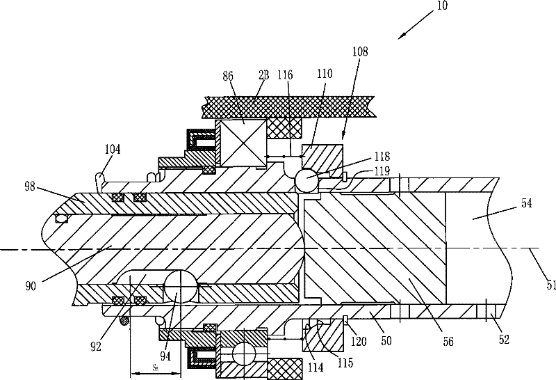
[0105] Refer to attached Figure 9-11, illustrates a hammer drill 1A of a second embodiment of the present invention. In the second embodiment, the basic structure of the hammer drill 1A is the same as that of the first embodiment, therefore, the reference numerals of the corresponding components are also the same. Only the different parts are explained here.

[0106] In this embodiment, the limit mechanism 208 limits the axial displacement of the punch 90 .

[0107] The punch 90 is in direct contact with the operating tool 28 . The punch 90 includes a front end in contact with the operating tool 28 and a rear end accommodated in the cylinder 50. A slide groove 92 is arranged radially from the outer wall and extends axially. A rolling element 94 is arranged between the cylinder 50 and the punch 90 and is accommodated in the slide groove. 92 , the punch 90 moves relative to the cylinder 50 between the end of the rolling member 94 located in the chute 92 adjacent to the front...

no. 3 example

[0120] Refer to attached Figure 12-15 , illustrates a hammer drill 1B of a third embodiment of the present invention. In the third embodiment, the basic structure of the hammer drill 1B is the same as that of the first embodiment, therefore, the reference numerals of the corresponding components are also the same. Only the different parts are explained here.

[0121] The limiting mechanism 308 limits the axial displacement of the impact block 56A.

[0122] The impact block 56A is accommodated in the cylinder 50 and can cross the through hole 52 in the axial direction, so as to keep the through hole 52 in fluid communication with the air chamber 54 or cut off the fluid communication between the through hole 52 and the air chamber 54 . When the through hole 52 is sealed, the impact block 56A will reciprocate in the cylinder 50 to exert an impact force on the punch 90 . Both the collet sleeve 98 and the punch 90 can move axially relative to the cylinder 50, and the amount of ...


PUM


Abstract

The invention discloses a hammer drill, which comprises a shell body, a motor arranged inside the shell body to generate rotating force, an operating tool, an impact force transfer mechanism and a switching mechanism. The impact force transfer mechanism comprises a gas cylinder, a piston, a motion conversion mechanism and a mobile element, wherein the gas cylinder can be rotationally supported inside the shell body and is provided with a first end and a second end; the first end and the second end can be axially extended; the operating tool is connected with the first end through a collet; the piston is arranged near the second end inside the gas cylinder and can move axially; the motion conversion mechanism can convert the rotating force of the motor into the reciprocation of the piston;the mobile element is arranged inside the gas cylinder and between the operating tool and the piston and can move axially; an air room is formed in the gas cylinder between the piston and the mobile element; and the gas cylinder is provided with at least a through hole for communicating the air room with the fluid outside the gas cylinder. The switching mechanism switches the operating mode between a first operating mode and a second operating mode; and the switching mechanism comprises a spacing mechanism which can restrict the displacement of the mobile element. The entire tool is compact in structure and low in manufacturing and assembly costs.

Description

technical field [0001] The present invention relates to a hammer drill including an impact force transmission mechanism that applies impact force to an operation tool and a rotation force transmission mechanism that transmits rotation force to the operation tool. Background technique [0002] At present, the hammer drill tools on the market have four operating modes according to different applications: the hammer drill mode that applies the impact force to the operating tool while driving the operating tool to rotate; the single drill mode that only drives the operating tool to rotate; A single-hammer mode in which an impact force is applied to an operating tool; and a hammer-angle mode in which a rotational force transmitted to an operating tool is mechanically interrupted. The conversion of these modes is usually realized by different operation mode switching mechanisms. [0003] U.S. Patent No. 6,116,352 discloses a hammer drill. A group of control air holes and a group ...

Claims


Application Information

Patent Timeline
Patent Type & Authority Patents(China)
IPC IPC(8): B25D16/00B25D17/00B25D17/08B25D17/02
Inventor 张士松顾育明
Owner POSITEC POWER TOOLS (SUZHOU) CO LTD
Why Eureka
Try Eureka