De-excitation device

A kind of demagnetization device, demagnetization resistance technology

Inactive Publication Date: 2010-03-10
WUHAN WUDA ELECTRIC POWER TECH
View PDF0 Cites 0 Cited by
  • Summary
  • Abstract
  • Description
  • Claims
  • Application Information

AI Technical Summary

Problems solved by technology

Therefore, there are many accidents caused by the failure of the demagnetization device, and the demagnetization device itself is the last safety measure in the generator system. Once the demagnetization device fails, the consequences are often very serious and the loss is also great.
The current main researches are all on improving the characteristics of the de-excitation switch, such as increasing the number of fractures of the de-excitation switch, improving the arc-resistant ability of the de-excitation switch, etc., but these often fail in some specific accidents, and the effect cannot make the people are satisfied

Method used


Image

  • De-excitation device
  • De-excitation device
  • De-excitation device

Examples


Embodiment Construction

[0023] The present invention will be further described below in conjunction with the accompanying drawings.

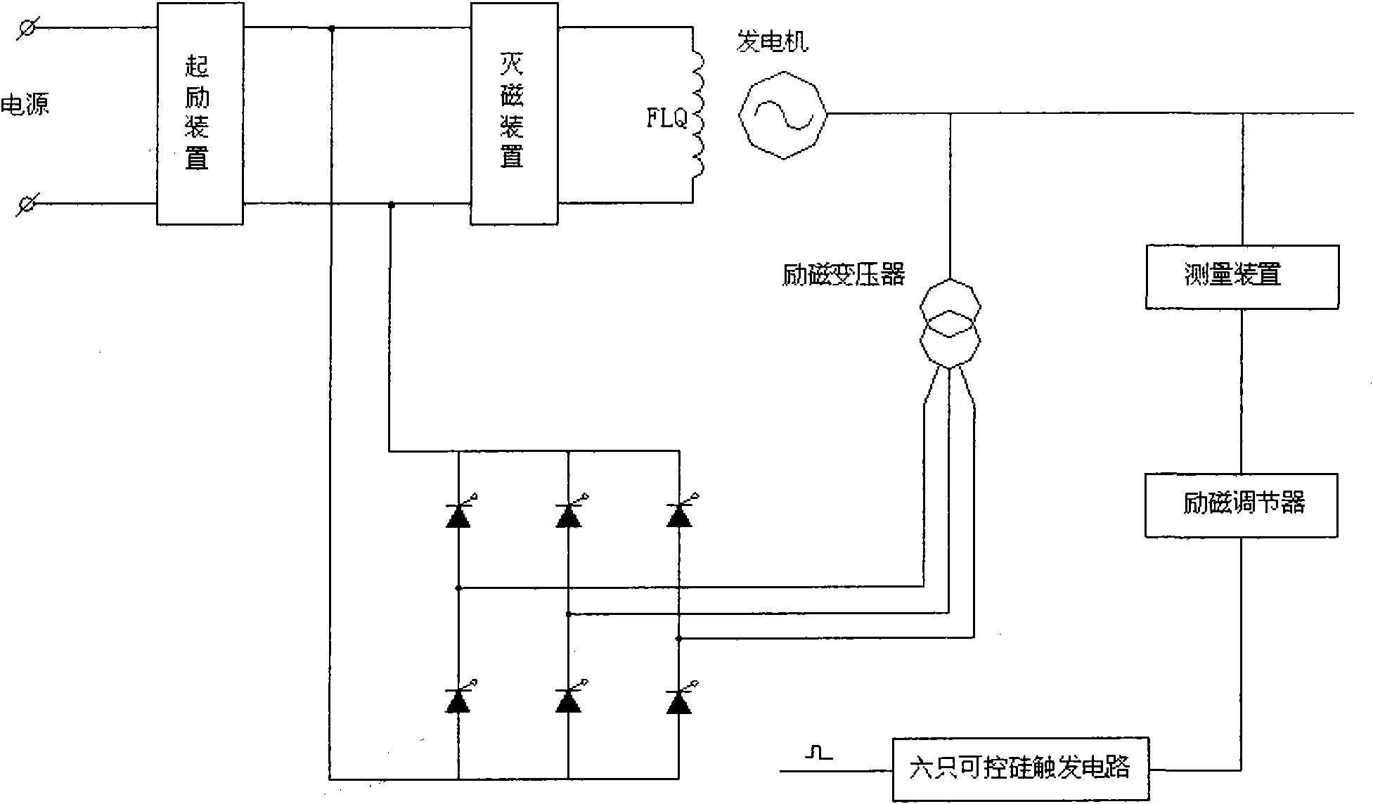
[0024] Such as figure 1 Shown is a traditional static excitation system, which includes excitation transformers, excitation regulators, thyristor rectifier bridges, de-excitation devices, measuring devices, thyristor trigger circuits, etc., wherein the thyristor rectifier bridges are all composed of thyristors .

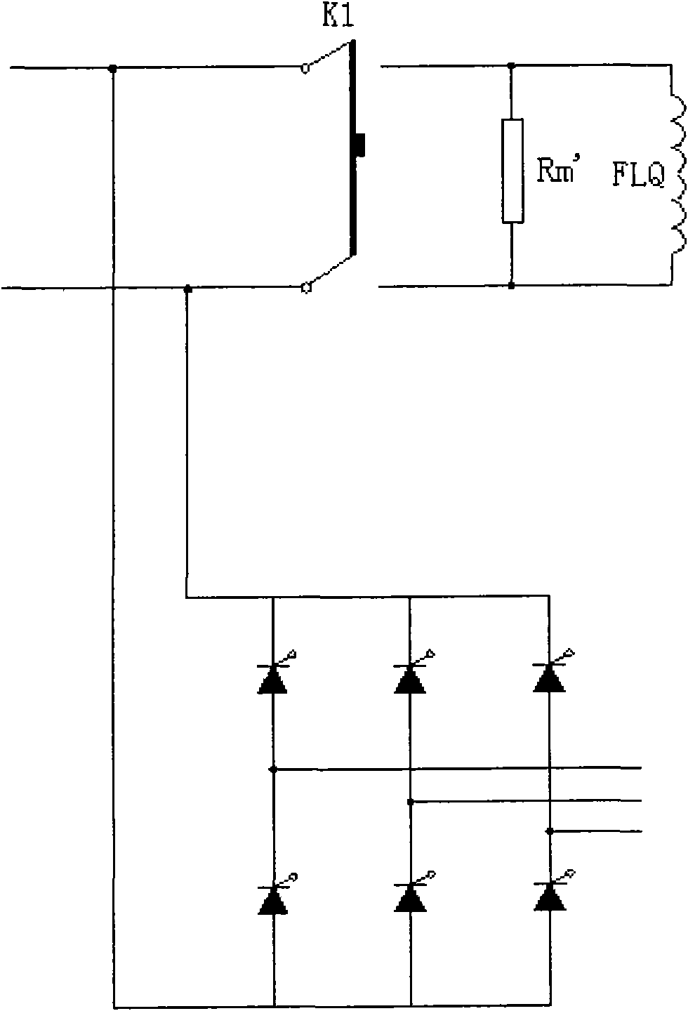
[0025] Such as figure 2 Shown is a schematic diagram of the de-excitation device in the traditional static excitation system. The traditional de-excitation method is to turn off the switch K1, separate the rectifier bridge from the excitation winding FLQ, and make the excitation winding FLQ and the de-excitation resistor Rm' form a loop to achieve the purpose of de-excitation.

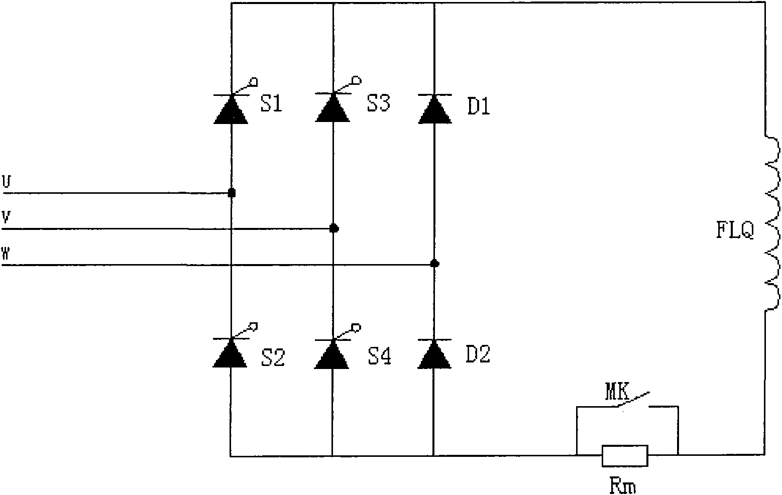
[0026] And the present invention provides a kind of new demagnetization technical scheme, as image 3 , Figure 4 As shown, the demagnetization device includes a rectifier bridg...


PUM


Abstract

The invention discloses a de-excitation device which comprises a rectifier bridge, a de-excitation resistor and a de-excitation switch, wherein the rectifier bridge comprises a silicon-controlled rectifier and diodes; one bridge arm of the rectifier bridge is connected with two diodes and the other bridge arms are connected with the silicon-controlled rectifier; and the de-excitation switch is connected with the de-excitation resistor in parallel and then connected with one output end of the rectifier bridge. The de-excitation device replaces two silicon-controlled rectifiers on one bridge armof the rectifier bridge in the traditional excitation system with dioxides which are then coordinated with the de-excitation switch for use, therefore, not only the controllability and the output value of the rectifier bridge are not influenced on the condition of rectification when in normal work, but also can the dioxides form a loop with the excitation winding so as to achieve the de-excitation function when de-excitation is required. The de-excitation device has the advantages of simple loop, convenient operation and high reliability.

Description

technical field [0001] The invention relates to the de-excitation technology of the generator excitation system, in particular to a de-excitation device in the static excitation system of the generator. Background technique [0002] At present, domestic generators mostly adopt static excitation mode. The static excitation system is composed of excitation transformer, excitation regulator, thyristor rectifier bridge, de-excitation device, measuring device and other parts. Each part plays a different role in the excitation system. The function of the de-excitation device is to quickly consume the energy in the rotor of the generator when the generator needs to be de-excited for some reason, so as to achieve the purpose of de-excitation. [0003] The degaussing device is mainly composed of a degaussing switch and a degaussing resistor. There are many types of degaussing switches, and there are several types of degaussing resistors, such as nonlinear resistance and linear resis...

Claims


Application Information

Patent Timeline
Patent Type & Authority Applications(China)
IPC IPC(8): H02H7/06
Inventor 江忠旭
Owner WUHAN WUDA ELECTRIC POWER TECH
Why Eureka
Try Eureka