Floor drain

A technology for floor drains and water leaks, applied in valve details, drainage structures, valve operation/release devices, etc., which can solve problems such as difficulty in opening cleaning and difficulty in removing seals.

Inactive Publication Date: 2010-03-10
耶特·威廉·瑟德斯特伦
View PDF0 Cites 1 Cited by
  • Summary
  • Abstract
  • Description
  • Claims
  • Application Information

AI Technical Summary

Problems solved by technology

However, these openings are small and cleaning can be difficult, and removing the seal can often be difficult

Method used


Image

  • Floor drain
  • Floor drain
  • Floor drain

Examples


Embodiment Construction

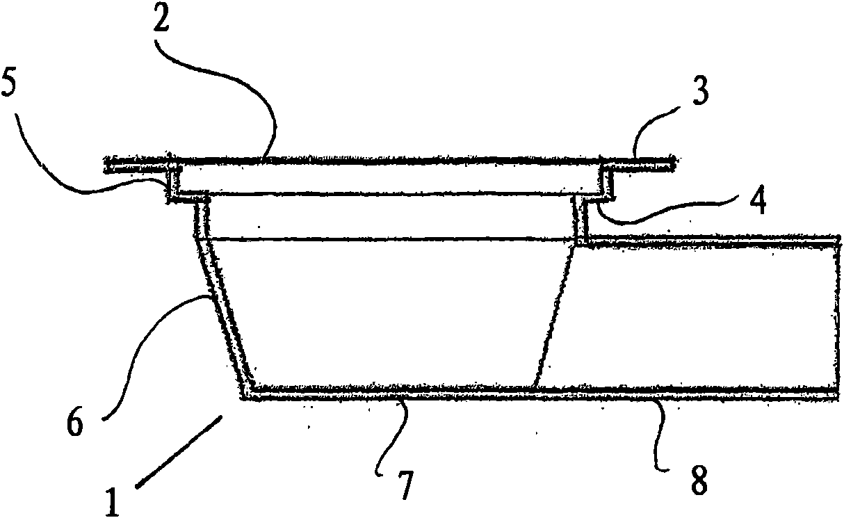
[0012] As is evident from the figures, the fixed main part 1 of the floor drain comprises an upper opening 2 and a circular flange 3 projecting radially from this opening. Just below the opening there is provided an inwardly extending step or shoulder 4 with a short cylindrical wall 5 between the shoulder and the opening. The fixed part 1 of the floor drain tapers slightly downwards towards the flat bottom 7 at the lower part 6 . Horizontal pipes 8 extend transversely for connection to the sewer system. Such as Figure 4 and 5 As seen in , above the shoulders, in the cylindrical wall 5 , alternating grooves 9 and ridges 10 are arranged.

[0013] exist Figure 5 shows how a floor material 11 eg in the form of a plastic floor or some other sealing layer is arranged on the floor drain and the sealing layer has been bent or formed down into the floor drain so that the bottom side will be in contact with said ridge 9 . The plastic floor material is pressed against the ridge 9 ...


PUM


Abstract

Floor drain with water trap including an upper screen (19, 28) or lip and a lower screen or threshold (32, 36) extending to a higher level than the lower edge of the upper screen, and that the water first flow below the upper screen and thereafter over the lower screen. The inlet part before the upper screen has a small cross-section or volume in relation to the water volume between the upper andthe lower screen securing an efficient flushing away of light pollutions.

Description

technical field [0001] The present invention relates to closed floor outlets or floor drains and water seals or water traps for floor outlets or floor drains for bathrooms, toilets, kitchens and the like. Background technique [0002] An unsatisfactory problem with floor drains is the cleanliness of the floor drain itself. If the drain is not kept clean, the risk is that organic matter accumulates in the drain, where it rots and emits an odor. Deposits can also occur in floor drains, causing them to clog. Removal and cleaning by chemical means needs to be performed frequently. Possibility of cleanup is made difficult by the water trap and the accumulation of organic pollutants is thereby enhanced. [0003] Water traps are used in floor drains to prevent air and odors from the sewer system from entering living spaces. In the water trap (odor seal), the outgoing water is forced to flow first under the first strainer and then over the second strainer, the upper edge of whic...

Claims


Application Information

Patent Timeline
Patent Type & Authority Applications(China)
IPC IPC(8): E03F5/04E03F5/042
CPCE03F5/042E03F2005/0416E03F7/02F16K31/18
Inventor 耶特·威廉·瑟德斯特伦
Owner 耶特·威廉·瑟德斯特伦
Why Eureka
Try Eureka