Terminal point for connecting a ring terminal to an electrical device

A technology of electrical equipment and connection points, applied in the direction of conductive connection, electrical component connection, connection, etc., can solve complex problems, achieve low cost, save space, and simplify the connection difficulty

Inactive Publication Date: 2010-03-10
SIEMENS AG
View PDF2 Cites 25 Cited by
  • Summary
  • Abstract
  • Description
  • Claims
  • Application Information

AI Technical Summary

Problems solved by technology

The downside is that the screw has to be removed from the connection point (i.e. the wiring point), i.e. the part is removed from the system during the connection process
This solution is more complex than the one above, requiring a larger part count and also requiring the use of a housing assembly for the terminal points to be anti-lost

Method used


Image

  • Terminal point for connecting a ring terminal to an electrical device
  • Terminal point for connecting a ring terminal to an electrical device
  • Terminal point for connecting a ring terminal to an electrical device

Examples


Embodiment Construction

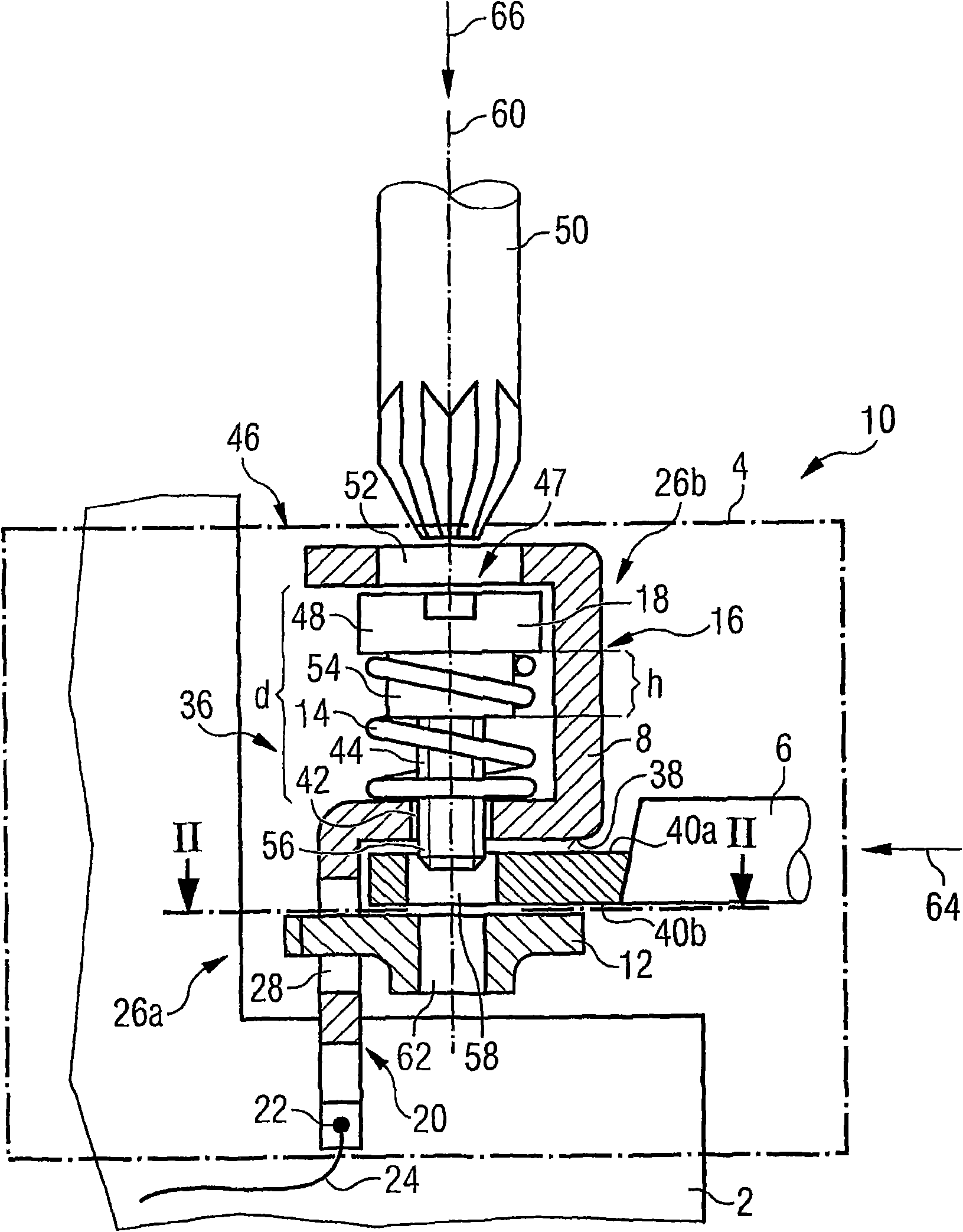
[0026] figure 1 The electrical device shown is a contactor 2 which includes a terminal 4 for a ring cable lug 6 on which an external lead (not shown in the figure) is crimped. The terminal 4 includes a bus bar or a contact holder 8 used as a connecting member and a clamping device 10 that is non-detachably mounted on the bus bar or the contact holder. The clamping device includes a threaded rail 12 used as a clamping plate and a clamping screw 18 that cooperates with the threaded rail, and the clamping screw is placed in position by a coil spring 14 figure 1 The release position 16 is shown.

[0027] The entire terminal 4 is installed in the contactor 2 with a fixed end 20 of the contact bracket 8, for example, encapsulated therein. The fixed end 20 is provided with a welding point 22 used as an equipment connector, and an internal connection wire 24 of the equipment is welded to the welding point, so that the terminal 4 is electrically connected to the inside of the equipment.

...


PUM


Abstract

The invention relates to a terminal point (4) for connecting a ring terminal (6) to an electrical device, comprising an electrically conductive connecting piece (8) having a device connection (22) anda clamping device (12, 18) displaceable relative to the connecting piece (8) for pressing the ring terminal (6) against a contact surface (38) of the connecting piece (8), wherein at least one part (26a, b) of the connecting piece (8) is designed as a mounting device (28, 30, 47) captively holding the clamping device (12, 18) on the connecting piece (8).

Description

Technical field [0001] The present invention relates to a connection point for connecting a ring cable lug to an electrical device. Background technique [0002] Many electrical devices have multiple connection terminals or multiple connection points for an external conductor. The known method is to install a ring cable lug on the conductor, and then clamp the conductor on the connection point by means of the ring cable lug. Conventional connection systems on the market (ie, connection points for a ring cable lug or cable joint) are now mainly composed of a contact element including a thread and a screw. At this time, the connection process of a ring cable lug consists of four connection steps: the first step is to unscrew the screw from the thread of the contact element; the second step is to insert the screw into the opening of the ring cable lug; Step, send the screw together with the ring cable lug into the wiring area (that is, the contact element or its thread); the fourt...

Claims


Application Information

Patent Timeline
Patent Type & Authority Applications(China)
IPC IPC(8): H01R4/30H01R4/38H01R11/12
CPCH01R4/305H01R4/301H01R4/30H01R4/38H01R11/12
Inventor 曼努埃尔·盖特纳沃尔夫冈·霍尔默
Owner SIEMENS AG
Why Eureka
Try Eureka