elevator equipment

A technology for elevators and equipment, used in elevators, lifts, transportation and packaging in buildings, etc., can solve the problems of rising manufacturing costs, reinforcement, and the height must be set below the top beam

Active Publication Date: 2011-12-14
HITACHI LTD +1
View PDF1 Cites 0 Cited by
  • Summary
  • Abstract
  • Description
  • Claims
  • Application Information

AI Technical Summary

Problems solved by technology

Therefore, a compressive load acts on the guide rail or support column on the side beyond the triangle, and a tensile load acts on the guide rail or support column on the side opposite to the above-mentioned excess side, so that the load appears to be concentrated in one part. The tendency on the guide rail or support column, thus, it is necessary to strengthen the strength of the above-mentioned guide rail and support column, which may lead to an increase in manufacturing cost
In addition, since the main sling fixed base side counterweight guide rail and the top beam support column are not vertically installed on the top of the hoistway, in buildings using steel structures, etc., the guide rail and the top beam support column The height that can be fixed on the building must be set below the top beam, so there is a problem that it is necessary to add members such as intermediate beams or fastening plates

Method used


Image

  • elevator equipment
  • elevator equipment
  • elevator equipment

Examples


Embodiment Construction

[0037] Embodiments of the present invention will be described below with reference to the drawings.

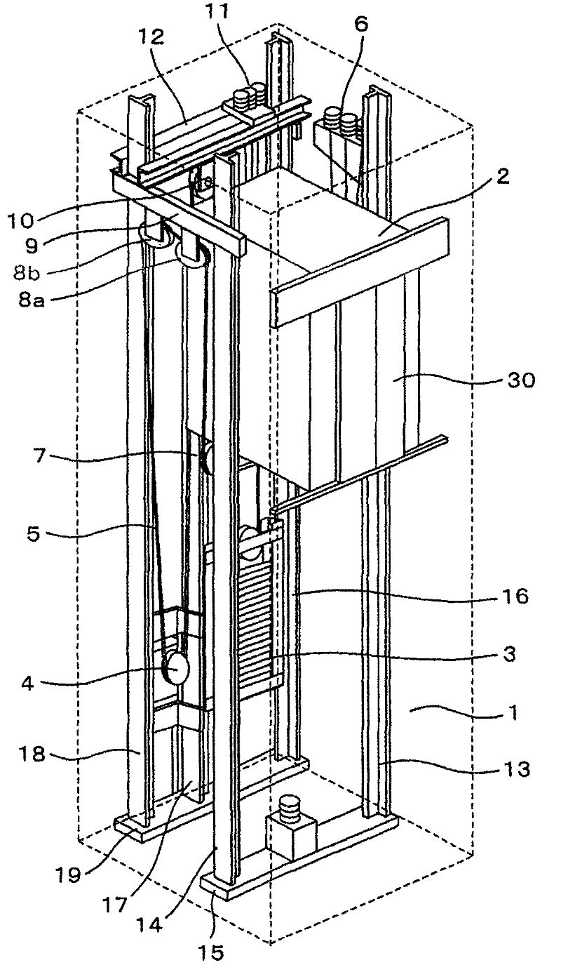
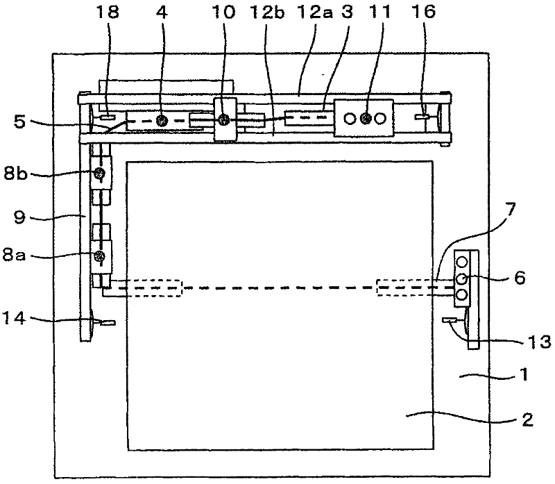
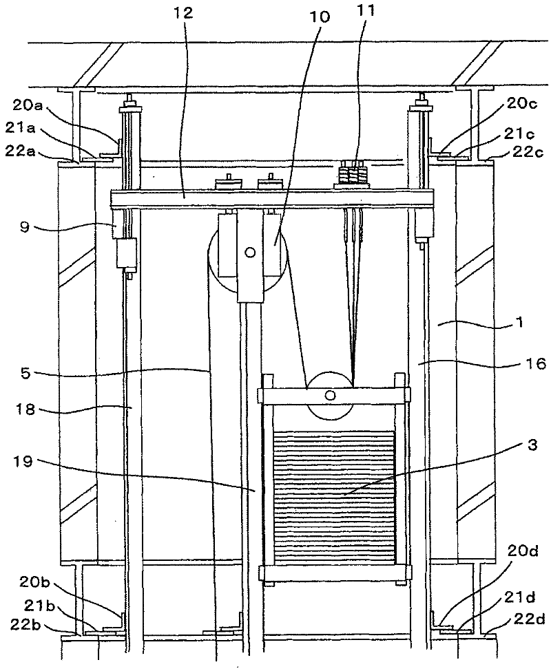
[0038] figure 1 It is a perspective view showing the outline of one embodiment of the elevator equipment of the present invention, figure 2 is a top view, image 3 It is a sectional view near the uppermost layer.

[0039] figure 1 The elevator shown is an elevator without a machine room formed in the hoistway 1 of the elevator. The sling 5 extends downward from the end of the main sling installed on the main sling fixing base 6 on the side of the elevator car and is wound around the lower car sheave 7 of the elevator car 2, and then returns upward to Suspend the elevator car 2, and then wind it on the elevator car side top sheave 8a, 8b (the elevator car side top sheave 8a, 8b is arranged on the elevator car side top beam 9 at the top of the hoistway) The upper and rear turns to extend downwards, and are wound on the sheave of the hoist 4 near the bottom floor, and then ...


PUM


Abstract

The present invention provides an elevator apparatus capable of reducing costs by virtue of a simpler structure without increasing the strength of guide rails. In the elevator equipment of the present invention, the load application point including the load application point installed on the sheave of the top beam and the load application point on the sheave of the hoisting machine is located in the area surrounded by the guide rails supporting these loads and the top beam support column. within the virtual polygon. It is possible to suppress local concentration of loads applied to the guide rails and the roof beam support columns. Therefore, there is no need to increase the strength of the guide rails and the top beam support columns, nor to increase the size of the guide rails and the top beam support columns.

Description

technical field [0001] The invention relates to an elevator installation without a machine room. Background technique [0002] In conventional elevator equipment, as described in Japanese Unexamined Patent Application Publication No. 2007-297209 (Patent Document 1), for example, it is configured such that the suspension load of the elevator car and the counterweight acts on the main ropes. The elevator car guide rails on the opposite side of the fixed base, the counterweight guide rails, the top sheave mounted on the top beam and the end of the main sling, the suspended load is composed of the elevator car side guide rails, the counterweight guide rails and the top beam The support column is supported, wherein the top beam is fixed on the upper part of the top beam support column. And, the counterweight guide rail is fixed on the upper surface of the elevator pit base, and the top beam support column is fixed on the upper surface of the elevator pit base via the hoist fixin...

Claims


Application Information

Patent Timeline
Patent Type & Authority Patents(China)
IPC IPC(8): B66B9/00B66B7/00B66B7/02B66B7/06
Inventor 西野克典萩谷知文
Owner HITACHI LTD
Why Eureka
Try Eureka