

Turn-plate detachable hydraulic gate
A technology for hydraulic gates and flat gates, applied in the field of detachable flap hydraulic gates, can solve the problems of increasing difficulty, the flap does not move, and the effect of the flap rotation is affected, so as to shorten the time and difficulty, and eliminate the effects of slippage.
Inactive Publication Date: 2010-03-17
ZHAOYANG PNEUAMTIC HYDRAULIC MECHANICAL EQUIP JIANGSU
View PDF0 Cites 0 Cited by
- Summary
- Abstract
- Description
- Claims
- Application Information
AI Technical Summary
Problems solved by technology
[0002] In the traditional gate structure, the flap of the gate is connected with the flap shaft after the entire gate is assembled and cannot be disassembled. Therefore, when the flap is damaged by the impact of mineral materials or excessively worn and needs to be replaced, it must be replaced. It will be removed together with the flap shaft, which will make the maintenance of the equipment too long and difficult, and sometimes even affect the operation of the entire system
[0003] At the connection between the shaft and the flap arm, the traditional connection method is the connection method of the square shaft and the square hole. The disadvantage of this connection method is that after the flap has been turned over for a long time, the edges and corners at the connection between the shaft and the hole are damaged. The rounding makes the shaft and the flap arm slip when they rotate, and often the shaft rotates but the flap does not move, which directly affects the rotation effect of the flap
Method used
View moreImage
Smart ImageViewing Examples

Examples
Embodiment Construction
[0011] Below in conjunction with accompanying drawing, the present invention is described in further detail:
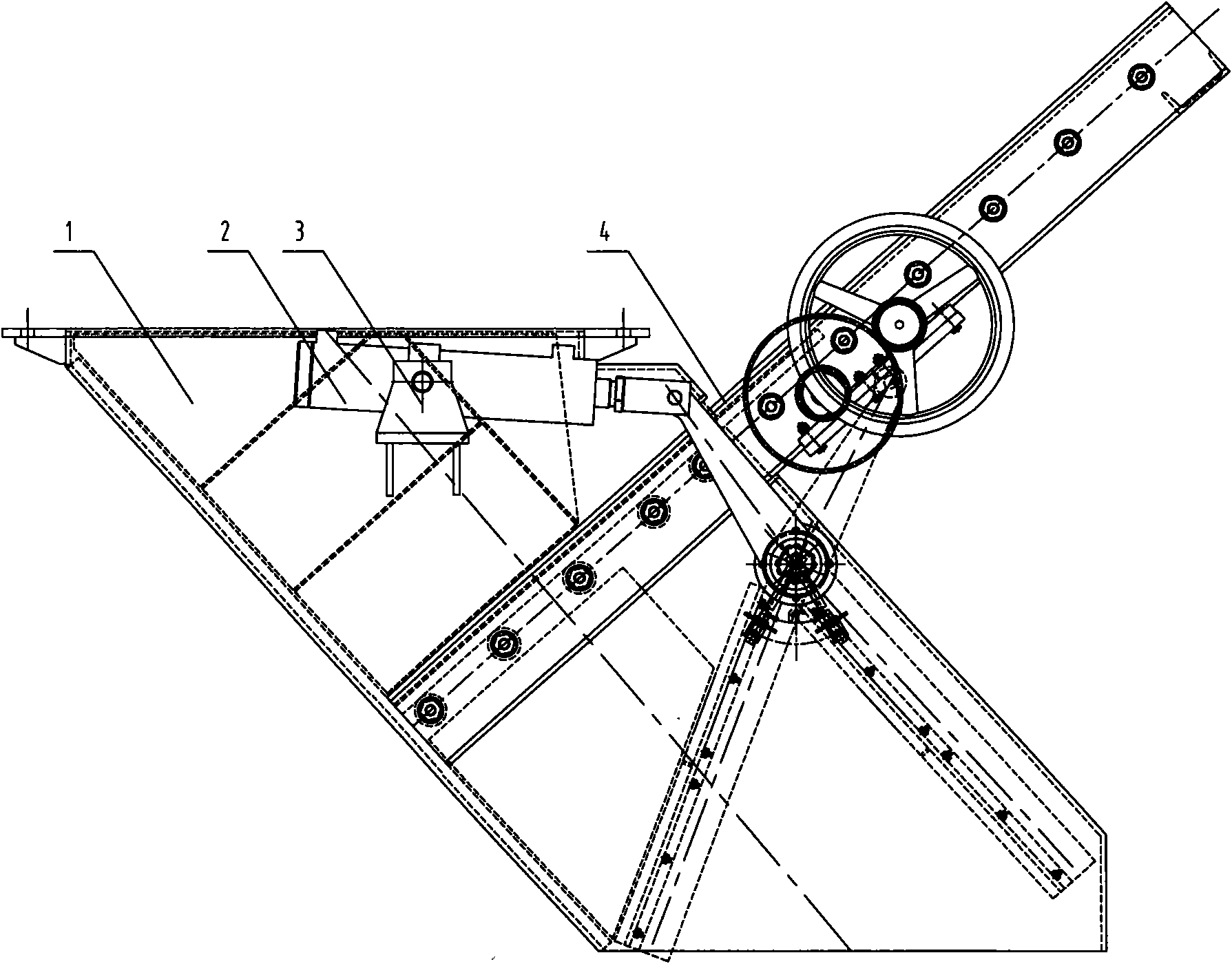
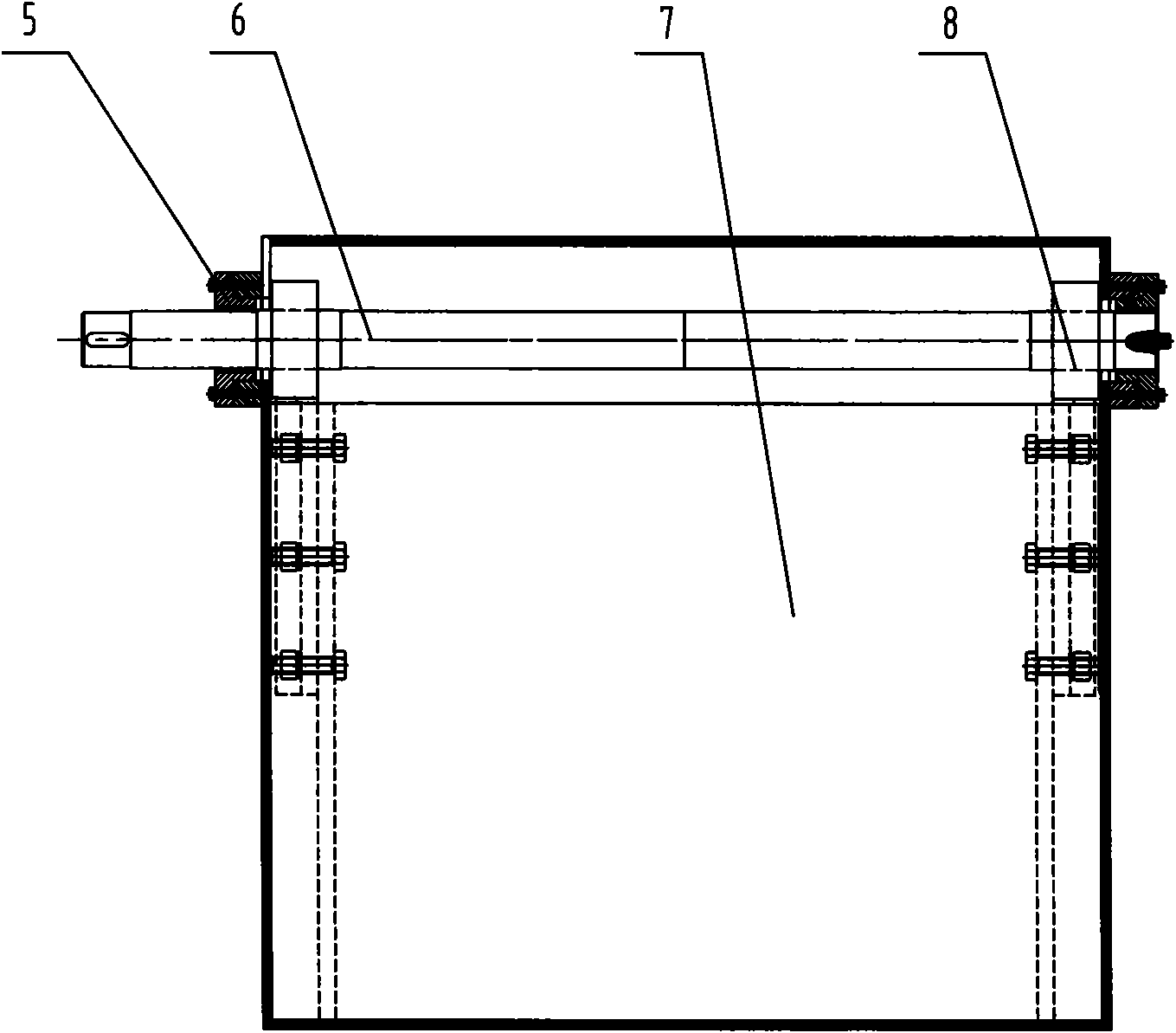
[0012] As shown in the attached figure, a hydraulic gate with a detachable flap includes a gate body 1, an oil cylinder 2, an oil cylinder bracket 3, a manual flat gate 4, a flap shaft seat 5, a flap shaft 6, a flap 7 and a flap Arm 8, an oil cylinder support 3 is installed on the gate body 1, an oil cylinder 2 is installed on the oil cylinder support 3, the manual flat gate 4 is connected with the oil cylinder 2, and a group of turning arms are added between the turning plate 7 and the turning plate shaft 6 8.
[0013] Set up a keyway on the 8 holes and the shaft of the flap arm.
Login to View More PUM
 Abstract
The invention provides a turn-plate detachable hydraulic gate, which comprises a gate body, an oil cylinder, an oil cylinder bracket, a manual plate gate, a turn-plate shaft seat, a turn-plate shaft,a turn plate and turn-plate arms, wherein the oil cylinder bracket is arranged on the gate body, the oil cylinder is arranged on the oil cylinder bracket, the manual plate gate is connected with the oil cylinder, and a group of turn-plate arms are additionally arranged between the turn plate and the turn-plate shaft. The turn-plate detachable hydraulic gate has the following advantages that: 1, the turn plate and the turn-plate shaft are connected together through the turn-plate arms, and only bolts between the turn plate and the turn-plate arms are detached to replace the turn plate when theturn plate needs to be replaced, so the time and difficulty of equipment maintenance are greatly reduced; and 2, in the turn-plate detachable hydraulic gate, key slots are increased on turn-plate armholes and the turn-plate shaft, so the slippage phenomenon between the turn-plate arms and the turn-plate shaft is basically eliminated under the action of the key slots.
Description
technical field [0001] The invention relates to a hydraulic gate, in particular to a hydraulic gate with a detachable flap. Background technique [0002] In the traditional gate structure, the flap of the gate is connected with the flap shaft after the entire gate is assembled and cannot be disassembled. Therefore, when the flap is damaged by the impact of mineral materials or excessively worn and needs to be replaced, it must be replaced. It is removed together with the flap shaft, which makes the maintenance time of the equipment too long, the difficulty will also increase, and sometimes even affect the operation of the entire system. [0003] At the connection between the shaft and the flap arm, the traditional connection method is the connection method of the square shaft and the square hole. The disadvantage of this connection method is that after the flap has been turned over for a long time, the edges and corners at the connection between the shaft and the hole are da...
Claims
Login to View More Application Information
Patent Timeline
 IPC IPC(8): F16K1/18F16K1/48F16K31/122
Inventor陈还喜陈翠萍张永农王海东
OwnerZHAOYANG PNEUAMTIC HYDRAULIC MECHANICAL EQUIP JIANGSU