
Pintle chain automatic assembly machine

An assembly machine and pin-joint chain technology, applied in the direction of metal chains, etc., can solve the problems of low assembly accuracy, low production efficiency, and large safety hazards, and achieve the effects of high assembly efficiency, low cost, and good assembly accuracy

Inactive Publication Date: 2010-03-24
ANHUI HUANGSHAN HENGJIU CHAIN TRANSMISSION CO LTD
View PDF0 Cites 58 Cited by
  • Summary
  • Abstract
  • Description
  • Claims
  • Application Information

AI Technical Summary

Problems solved by technology

Although the process has the advantages of simple operation and low assembly cost, it has defects such as low assembly accuracy and bump damage caused by manual assembly and reordering. In particular, it has a large amount of manual work, low production efficiency, and poor product quality. Stable, with great security risks, difficult to adapt to the competitive requirements of the product market

Method used


Image

  • Pintle chain automatic assembly machine
  • Pintle chain automatic assembly machine
  • Pintle chain automatic assembly machine

Examples


Embodiment Construction

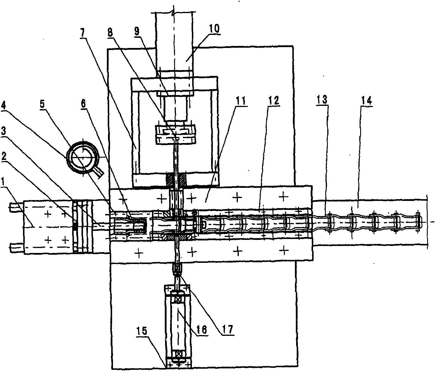
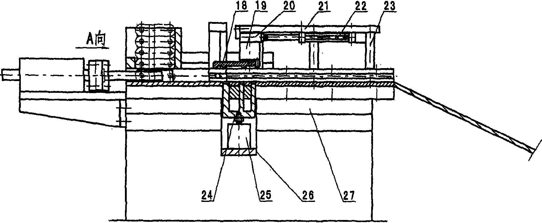
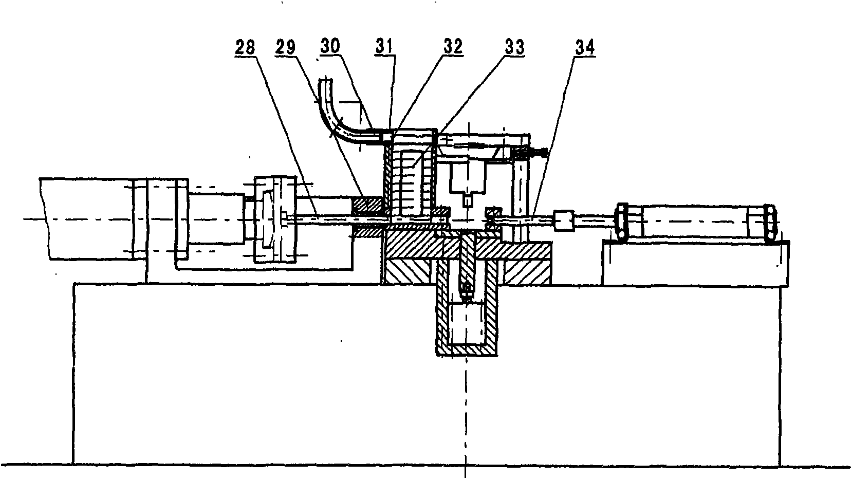
[0009] Such as figure 1 , 2 , As shown in 3, a pin-joint chain automatic assembly machine is composed of a chain plate feeding mechanism, a chain plate positioning mechanism, a chain pin feeding and pin threading mechanism, a chain link transfer mechanism and a frame, a discharge plate and PLC automatic control The Pin Chain Assembly Machine.

[0010] The chain plate feeding mechanism is composed of a double-column feeding cylinder arranged on the front side of the frame 27, a feeding rod and a chain feeding plate. The cylinder rod of the double-column feeding cylinder 1 is connected with the feeding rod 3 through the cylinder connection seat 2 . Feeding chain plate closes 5 and is installed on the top of the parallel track 12 that is formed by the left and right parallel track fixed seat 11 that is provided with on the frame platen, and its below offers the through groove that is parallel with parallel track. The chain plate 6 in the chain plate is pushed forward steadily ...


PUM


Abstract

The invention relates to a pintle chain automatic assembly machine, belonging to the technical field of chain manufacturing machinery. The invention aims to provide a pintle chain automatic assembly machine which is suitable for the assembly production process of pintle chains and has good precision control and high production efficiency. The technical key of the pintle chain automatic assembly machine in that the assembly machine comprises a frame, a link plate feeding mechanism, a link plate positioning mechanism, a pin-penetrating mechanism, a chain element moving mechanism, a PLC automaticcontrol system and a discharging plate, wherein the link plate feeding mechanism comprises a double-cylinder feeding air cylinder (1) and a feeding pole (3) which are arranged in the front of the frame (27) and a link plate-feeding box (5); the link plate positioning mechanism comprises a positioning air cylinder (25) and a positioning block (24) which are arranged below the platen of the frame;the chain pin feeding and pin-penetrating mechanism comprises a pin-pressing air cylinder (10) and a pin-introducing air cylinder (16) which are arranged on the two sides of the parallel track of theplaten of the frame and a vibration pin-distributing disk (4), a pin-sending hose (30) and a pin-collecting box (32) which are arranged on the platen of the frame; the chain element moving mechanism comprises a moving air cylinder (22) and a chain element-pressing air cylinder (19) which are arranged above the platen of the frame; the discharging plate (14)is arranged on the backside of the platenof the frame.

Description

technical field [0001] The invention relates to an automatic assembly machine for pin-joint chains, which belongs to the technical field of chain manufacturing machinery. Background technique [0002] Chain is an important power transmission part in mechanical equipment, and its application is extremely extensive. The pin chain is a transmission part used for wood transportation, which is assembled in series by chain plates and pins. Due to its structural characteristics, in the current assembly process of pin-joint chains, the assembly tasks of chain plate loading, pin threading and pin pressing are mainly completed by manual operations. Although the process has the advantages of simple operation and low assembly cost, it has defects such as low assembly accuracy and bump damage caused by manual assembly and reordering. In particular, it has a large amount of manual work, low production efficiency, and poor product quality. Stable, with great security risks, it is difficu...

Claims


Application Information

Patent Timeline
Patent Type & Authority Applications(China)
IPC IPC(8): B21L9/06
Inventor 陈亦兵程国东程移风汪恒木胡建树汪明璜许坚石黄全忠陈忠何曙光章毓林胡晓勇
Owner ANHUI HUANGSHAN HENGJIU CHAIN TRANSMISSION CO LTD
Learn More