Supercharge Your Innovation With Domain-Expert AI Agents!

Work machine

A technology of working machinery and pressurization mechanism, which is applied in the direction of manufacturing tools, metal processing, boring/drilling, etc., and can solve problems that cannot be ignored

Inactive Publication Date: 2010-03-24
NT ENGINEERING CO LTD
View PDF1 Cites 2 Cited by
  • Summary
  • Abstract
  • Description
  • Claims
  • Application Information

AI Technical Summary

Problems solved by technology

As a result, the influence of the centrifugal force generated in the boring bar cannot be ignored, and a boring processing device that can suppress changes in the centrifugal force even when the tool nose is corrected and moved

Method used


Image

  • Work machine
  • Work machine
  • Work machine

Examples


Embodiment Construction

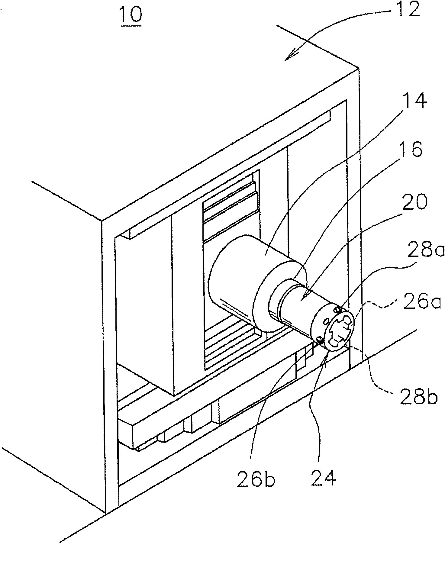
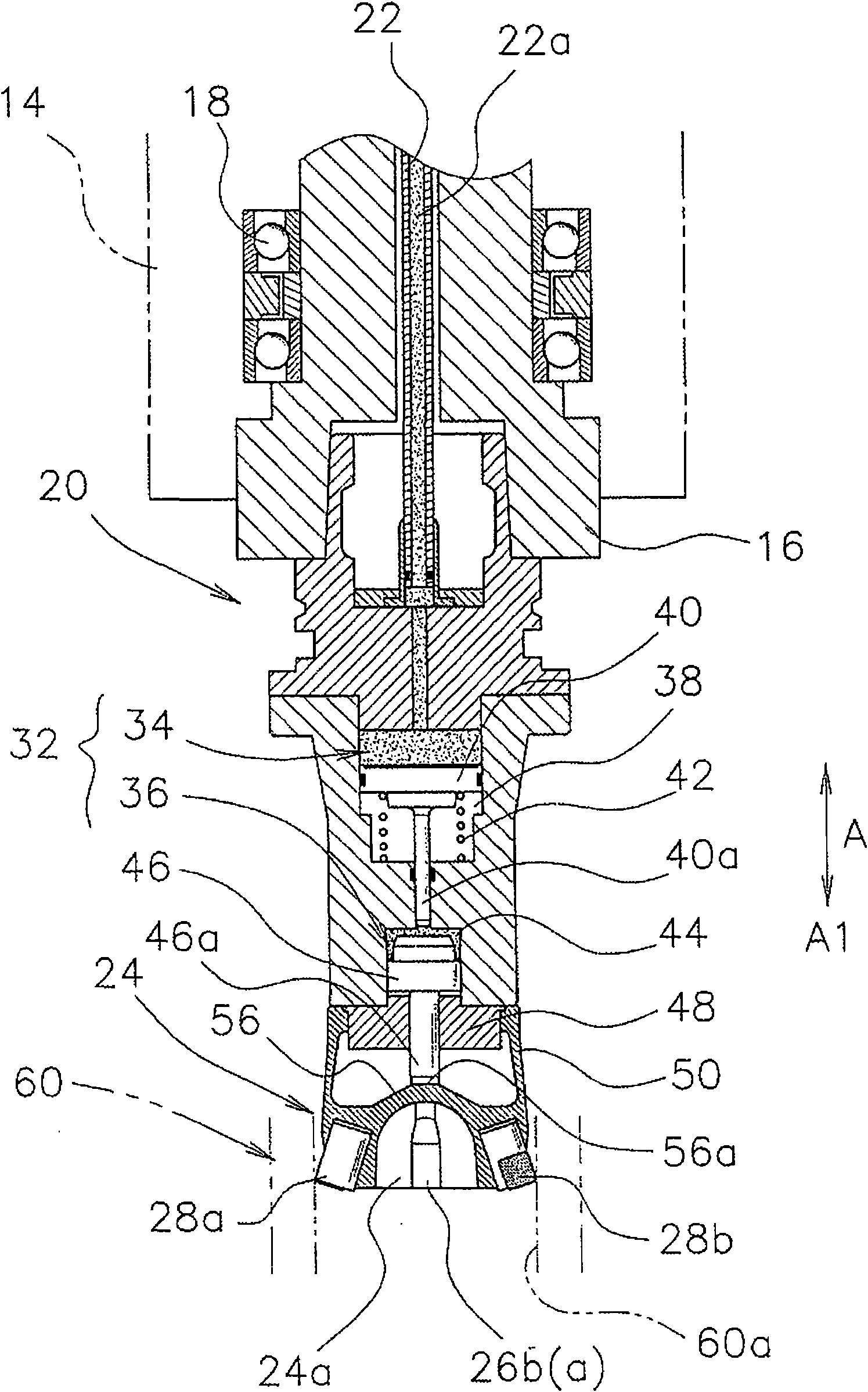
[0030] figure 1 It is a perspective explanatory view of a working machine 10 as a working machine according to the first embodiment of the present invention, figure 2 It is a cross-sectional explanatory view of the aforementioned machine tool 10 .

[0031] The machine tool 10 includes a main body portion 12 , and a housing 14 is slidably attached to the main body portion 12 . A main shaft (spindle) 16 is rotatably provided in the casing 14 via a bearing 18 , and a tool holder 20 is detachably attached to the main shaft 16 .

[0032] Such as figure 2 As shown, in the housing 14, a gas conduit 22 is arranged along the axis of the main shaft 16, and a gas passage 22a communicating with an unillustrated gas supply source is formed in the gas conduit 22.

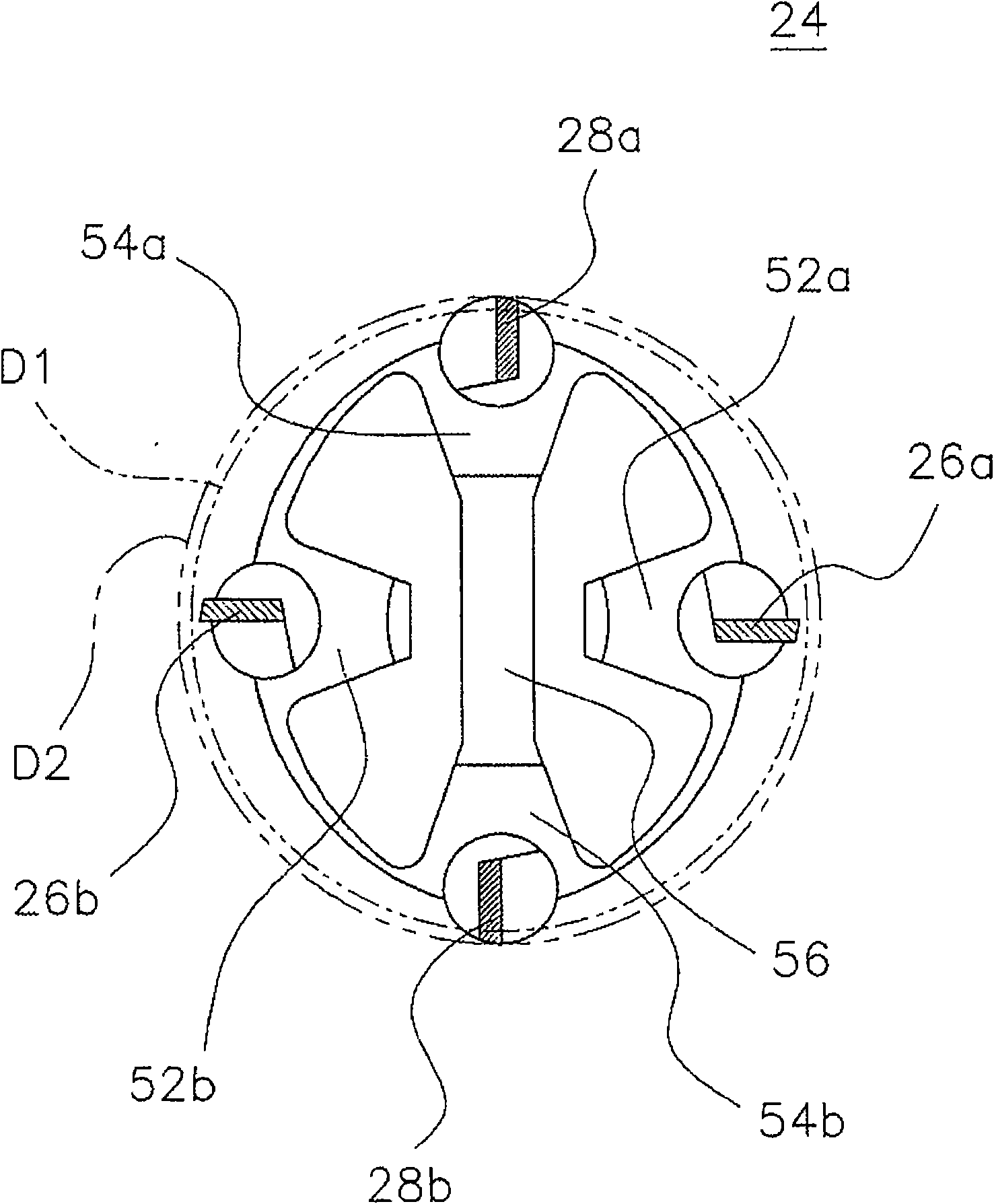
[0033] An annular elastic retainer portion 24 is mounted on the blade holder 20 . One end of the annular elastic holder portion 24 is fastened to the blade holder 20 and the other end forms an open end portion 24 a. Two or ...


PUM


Abstract

A work machine in which a tool attached to a tool holder performs highly accurate work. This is achieved by adapting the tool holder to be adjustable in the radial direction and by preventing a changein centrifugal force as much as possible. An annular elastic holder part (24) having one end secured to the tool holder (20) and the other end forming an open end (24a) is attached to the tool holder(20). Two or more tools, such as semi-finishing blades (26a, 26b) and finishing blades (28a, 28b), are fitted to the open end (24a). A pressing mechanism (32) is installed in the tool holder (20), and the pressing mechanism (32) moves forward and backward in the axial direction of the tool holder (20) to press the annular elastic holder part (24), deforming the open end (24a) into an elliptic shape. When the opening end (24a) is deformed in the elliptic shape, the semi-finishing blades (26a, 26b) move radially inward and the finishing blades (28a, 28b) move radially outward.

Description

technical field [0001] The present invention relates to a work machine in which two or more tools are attached to a tool post that is rotatable integrally with a main shaft. Background technique [0002] In general, various machine tools (work machines) are used that process workpieces via tools mounted on tool holders, such as machining tools. For example, in the boring process of the cylinder constituting the engine block, it is necessary to process the diameter dimension of the inner cylinder with precision level and high precision. Therefore, generally, boring is performed in three steps of rough boring (rough machining), semi-finish boring (semi-finishing), and finish boring (finishing). [0003] In this type of boring, especially fine boring, it is necessary to form a high-precision machining diameter and perform machining with a single edge. However, in the fine boring process performed by mass-production equipment, since a single cutting edge is used for processing...

Claims


Application Information

Patent Timeline
IPC IPC(8): B23B39/00
CPCB23B2250/08B23C2270/027B23B2260/004B23B29/03457B23B2270/025B23B2270/06B23B2265/16B23B41/12B23B39/00B23B39/04B23B41/16
Inventor 驹井保宏
Owner NT ENGINEERING CO LTD
Features
  • R&D
  • Intellectual Property
  • Life Sciences
  • Materials
  • Tech Scout
  • Unparalleled Data Quality
  • Higher Quality Content
  • 60% Fewer Hallucinations
Learn More