Liquid-cooled internal combustion engine

A liquid cooling, internal combustion engine technology, applied in liquid cooling, engine cooling, mechanical equipment, etc., can solve problems such as affecting the passage of coolant, uncooled areas of the bushing, and disadvantages

Active Publication Date: 2010-03-24
AVL LIST GMBH
View PDF1 Cites 7 Cited by
  • Summary
  • Abstract
  • Description
  • Claims
  • Application Information

AI Technical Summary

Problems solved by technology

The disadvantage is that the area of ​​the bushing is not cooled sufficiently
Another disadvantage is that the flow direction of the upper part cooling chamber into the cooling jacket of the cylinder housing through the bottom part cooling chamber creates a reverse thermosiphon effect in the entire cooling system, which adversely affects the passage of the coolant, in This is especially true when working in an emergency

Method used


Image

  • Liquid-cooled internal combustion engine
  • Liquid-cooled internal combustion engine

Examples


Embodiment Construction

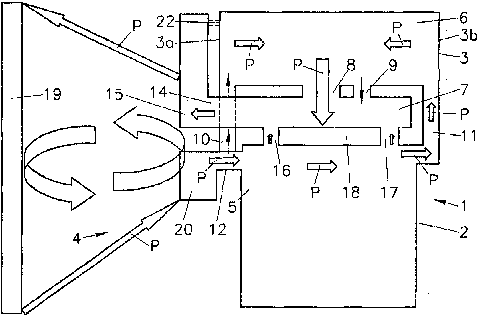
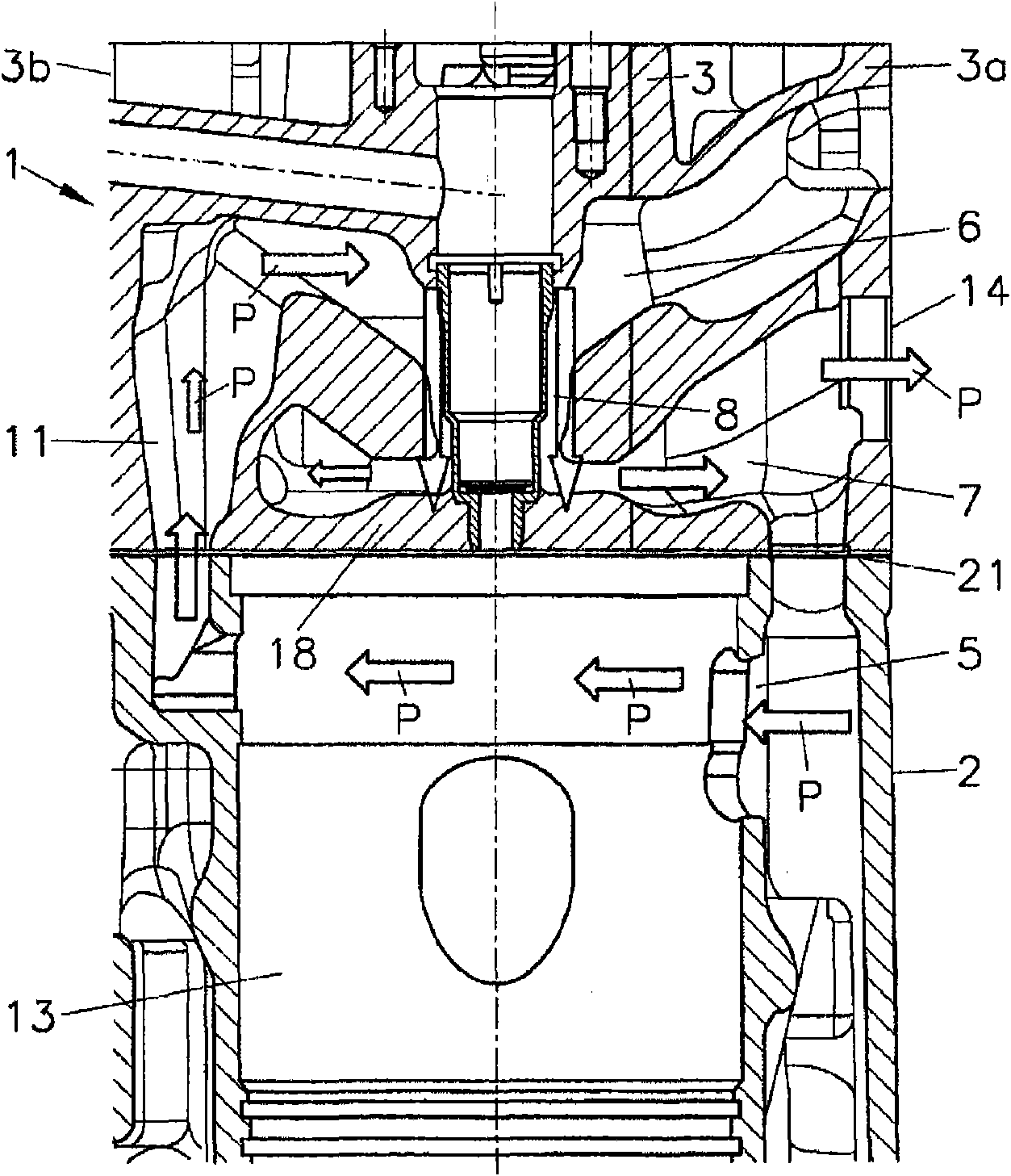
[0012] Internal combustion engine 1 includes a cylinder housing 2 and a cylinder head 3 . The cooling system 4 is arranged for cooling with a cooling fluid which flows through the cooling cylinder jacket 5 in the cylinder housing 2 and the upper and bottom part cooling chambers 6 , 7 in the cylinder head 3 . The upper part cooling chamber 6 and the bottom part cooling chamber 7 are fluidly connected by at least one transfer hole 8, 9 per cylinder. Vertical manifolds 10 , 11 are arranged on opposite longitudinal sides 3 a , 3 b of the cylinder head 3 , which connect the upper part cooling chamber 6 with the cooling jacket 5 of the cylinder housing 2 . The cooling jacket 5 of the cylinder housing 2 is connected via at least one coolant inlet 12 per cylinder 13 to a coolant distribution chamber 20 extending on the longitudinal side 3 a. The bottom part cooling chamber 7 opens via at least one coolant outlet 14 in each cylinder 13 into a coolant collection chamber 15 arranged on ...


PUM


Abstract

The invention relates to a liquid-cooled internal combustion engine (1) comprising a cylinder housing (2) for at least one cylinder (13) and at least one cylinder head (3). The at least one cylinder (13) in the cylinder housing (2) is surrounded by a cooling jacket (5). A lower partial cooling chamber (7) that adjoins a fireproof cover (18) and an upper partial cooling chamber (6) which is fluidically connected to the lower partial cooling chamber (7) via at least one overflow port (8, 9) are disposed in the cylinder head (3), which is connected to the cylinder housing (2). A coolant outlet (14) that can be connected to a pressure sink extends from the lower partial pressure chamber (7). In order to improve cooling, at least one coolant inlet (12) that can be connected to a pressure sourceextends into the cooling jacket (5) of the cylinder housing (2), and the cooling jacket (5) is directly fluidically connected to the upper partial cooling chamber (6) via at least one riser (10, 11)such that coolant flows from the pressure source into the cooling jacket (5) of the cylinder housing (2), from the cooling jacket (5) into the upper partial cooling chamber (6) of the cylinder head (3) and on into the lower partial cooling chamber (7) via the overflow port (8, 9), and from the lower partial cooling chamber (7) to the pressure sink during operation of the engine.

Description

technical field [0001] The invention relates to a liquid-cooled internal combustion engine comprising a cylinder housing comprising at least one cylinder and at least one cylinder head, wherein the at least one cylinder located in the cylinder housing is closed by a cooling cylinder liner and the bottom part cooling chamber is adjacent A fire deck is provided, while the upper part cooling chamber is in fluid communication with the bottom part cooling chamber through at least one transfer opening arranged in the cylinder head, the cylinder head is connected to the cylinder housing, and the coolant outlet is connected to the pressure The tanks are connected, and the pressure tank starts from the cooling chamber in the bottom part. Background technique [0002] AT005939U1 discloses a cylinder head for a liquid-cooled internal combustion engine having a cooling chamber arrangement adjacent to the ignition platform, an intermediate platform substantially parallel to the ignition ...

Claims


Application Information

Patent Timeline
Patent Type & Authority Applications(China)
IPC IPC(8): F01P3/02F02F1/38
CPCF02F1/242F01P2003/028F01P3/02F02F1/40
Inventor R·珀斯彻尔A·恩纳莫瑟尔M·布雷顿勃格
Owner AVL LIST GMBH
Why Eureka
Try Eureka