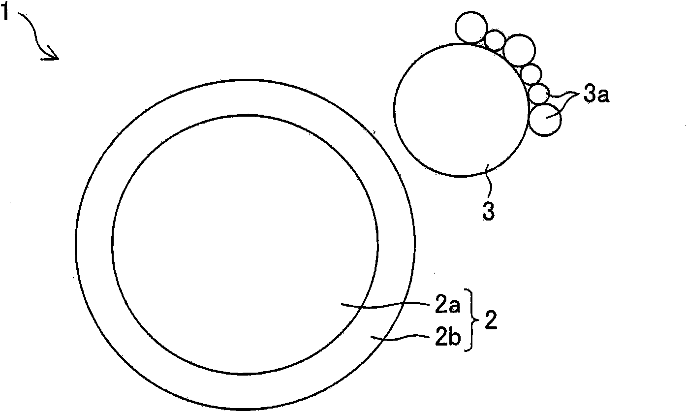
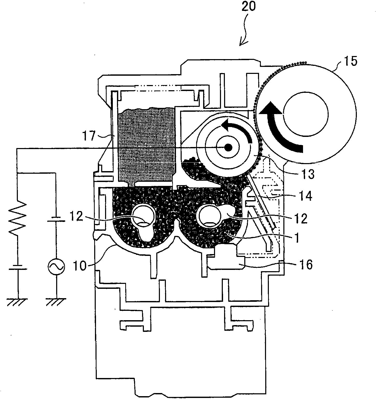
Magnetic carrier, two-component developer, developing unit, developing device, image-forming apparatus, and image-forming method
A technology of magnetic carrier and developing unit, which is applied in the direction of developer, electric recording process applying charge pattern, equipment applying electric recording process of electric charge pattern, etc., can solve problems such as increasing adhesion, and achieve the effect of stable output
- Summary
- Abstract
- Description
- Claims
- Application Information
AI Technical Summary
Problems solved by technology
Method used
Image
Examples
Embodiment 1
[0128] According to the method described above (Preparation of Resin-Coated Carrier), a resin-coated carrier was produced by applying a coating resin solution in which the content of the charge control agent was gradually changed in units of 5 parts by weight within the range of 0 to 20 parts by weight. . The resistance value of each resin-coated carrier was measured according to the method described above (Measurement of Resistance Value of Carrier Particles).
[0129] In addition, using the toner for cyan color evaluation prepared by the method described above (Preparation of toner), and each of the above-prepared resin-coated carriers containing conductive particles in different amounts (different in electrical resistance), two samples were produced. Component developer. The two-component developer is injected into the developing cartridge A. Using the test bench described above (evaluation of the degree of image blurring of carrier adhesion and background part), after id...
Embodiment 2
[0146] Magnetic core particles having different resistance values were prepared, and the resistance value was measured according to the above (measurement of resistance value of magnetic core particles). Next, the surfaces of the magnetic core particles having these resistance values were coated with resin according to the method described above (Preparation of Resin-Coated Carrier) to prepare a resin-coated carrier.
[0147] Next, a two-component developer was prepared by using the toner for cyan color evaluation prepared by the method described above (Preparation of Toner) and resin-coated carriers each having a different resistance. Inject each two-component developer into the developing ink cartridge A respectively, apply the test bench described in the above (evaluation of the degree of image blurring of carrier adhesion and background part), and carry out idling for 3 minutes under normal temperature and normal humidity conditions, and then apply the test bench to the...
Embodiment 3
[0153] A resin-coated carrier was produced by preparing magnetic core particles having different volume-average particle diameters and performing resin coating according to the method described above (Preparation of Resin-Coated Carrier). Next, each resin-coated carrier produced using magnetic core particles having different volume average particle diameters was evaluated in accordance with the above (evaluation of degree of carrier adhesion and background part image blurring). The evaluation results are shown in Table 3.
[0154] [table 3]
[0155]
[0156] It can be seen from Table 3 that when the volume average particle diameter of the resin-coated carrier is 20 μm or less, the magnetic roller wrapped in the developer carrier will reduce the holding force of the resin-coated carrier, and the resin-coated carrier will easily adhere to static electricity. Latent image carrier surface. Furthermore, it tends to be unevenly mixed with the toner, and the charge distribution ...
PUM
 Abstract
Description
Claims
Application Information
 - R&D
- Intellectual Property
- Life Sciences
- Materials
- Tech Scout
- Unparalleled Data Quality
- Higher Quality Content
- 60% Fewer Hallucinations
Browse by: Latest US Patents, China's latest patents, Technical Efficacy Thesaurus, Application Domain, Technology Topic, Popular Technical Reports.
© 2025 PatSnap. All rights reserved.Legal|Privacy policy|Modern Slavery Act Transparency Statement|Sitemap|About US| Contact US: help@patsnap.com


