A diffractive beam expander and a virtual display based on a diffractive beam expander

A beam expander and light diffraction technology, applied in the field of displaying virtual images, to achieve the effects of improving the quality of the output beam, improving the parallelism of the out-coupled beam, and fully outputting the beam quality

Active Publication Date: 2010-03-31
MAGIC LEAP
View PDF3 Cites 105 Cited by
  • Summary
  • Abstract
  • Description
  • Claims
  • Application Information

AI Technical Summary

Problems solved by technology

However, the small size of portable devices also places a limit on the size of the displays contained in said devices
A typical disadvantage of t...

Method used


Image

  • A diffractive beam expander and a virtual display based on a diffractive beam expander
  • A diffractive beam expander and a virtual display based on a diffractive beam expander
  • A diffractive beam expander and a virtual display based on a diffractive beam expander

Examples


Embodiment Construction

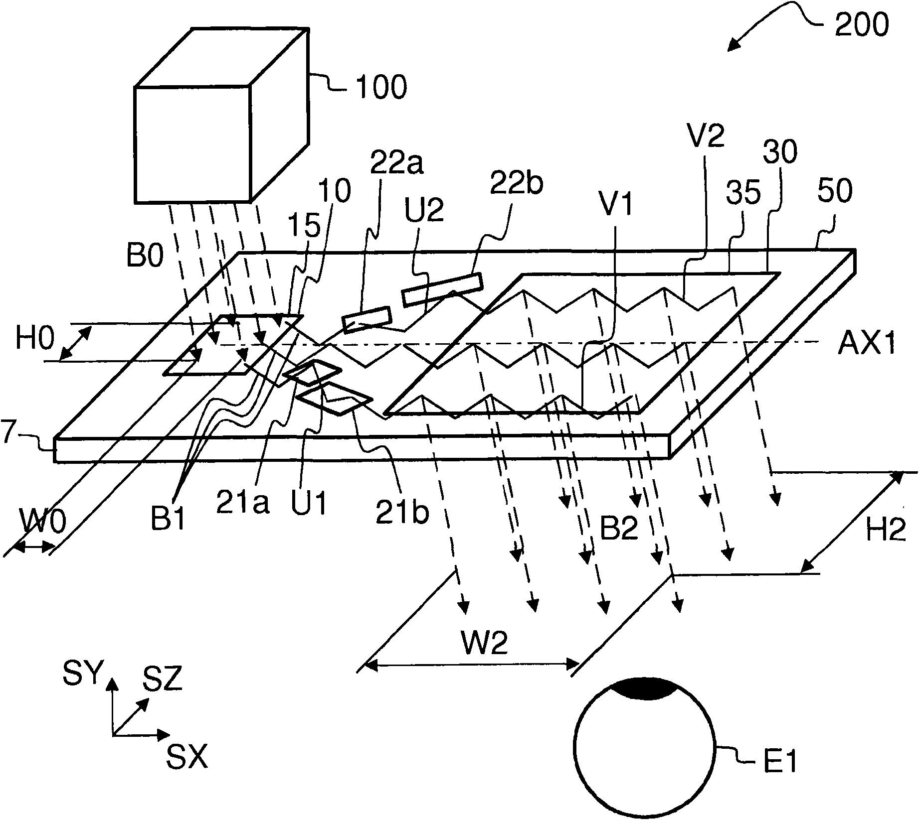
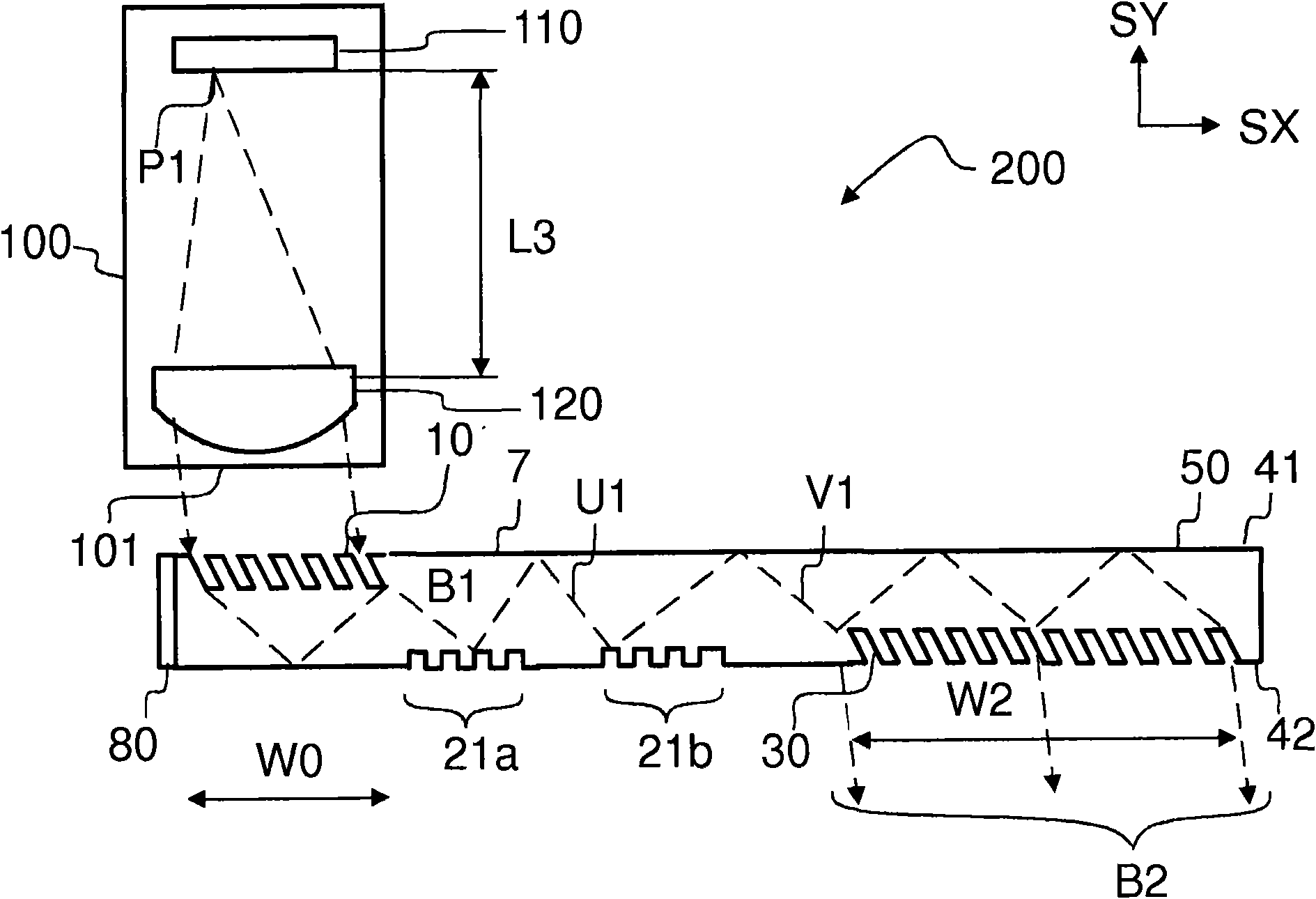
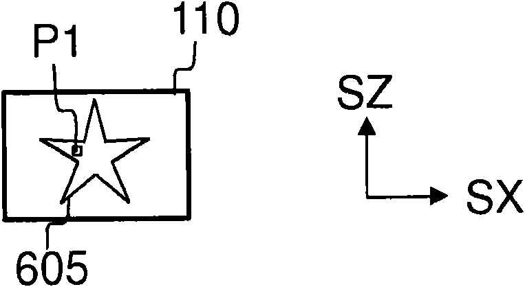
[0045] refer to figure 1 , the virtual display device 200 may include an optical engine 100 and a diffractive beam expander 50 . Optical engine 100 may include microdisplay 110 and imaging optics 120 ( Figure 2a ). The imaging optics 120 transforms the real image 605 formed by the microdisplay 110 ( Figure 2b ) into a virtual image 710 ( Figure 14 ), the virtual image 710 is observable through the viewing aperture 35 of the diffractive beam expander 50.

[0046] The diffractive beam expander 50 may include: an input grating 10 ; two or more beam deflecting grating sections 21 a , 22 a ; two or more direction restoring sections 21 b , 22 b ; and an output grating 30 . The gratings 10 , 30 and the grating sections 21 a , 22 a , 21 b , 22 b can be realized on a substantially planar transparent substrate 7 . The substrate 7 has a first substantially planar surface, and a second substantially planar surface substantially parallel to said first planar surface.

[0047] The ...


PUM


Abstract

A diffractive beam expander (50) comprises a substantially planar waveguiding substrate, an input grating (10) to provide an in-coupled beam (B1) propagating within said substrate, and an output grating (30) to provide an out-coupled beam. The expander (50) comprises also four or more further grating portions to expand the height of the in-coupled beam (B1). A part of the in-coupled light is diffracted by a first deflecting grating portion (21a) to provide a first deflected beam. A part of the in-coupled light is diffracted by a second deflecting grating portion (22a) to provide a second deflected beam. The first deflected beam propagates downwards and the second deflected beam propagates upwards with respect to the in-coupled beam (B1). The first deflected beam impinges on a first direction-restoring grating portion (21b) and the second deflected beam impinges on a second direction-restoring grating portion (22b). The first restoring grating portion (21b) provides a first restored beam (V1) and the second restoring grating portion (22b) provides a second restored beam (V2), which both have the same direction as the in-coupled beam (B1). Out-coupling provides an output beam which is parallel to the input beam, and has a greater vertical dimension than said input beam.

Description

technical field [0001] The present invention relates to expanding light beams by means of diffractive elements. The invention also relates to displaying virtual images. Background technique [0002] Display modules are used in portable devices to display information in graphical form. Small size is an important aspect in portable devices. However, the small size of portable devices also places a limit on the size of the displays contained in said devices. A typical disadvantage of traditional small displays is that the viewer can only see a small portion of the large image displayed at a time while maintaining sufficient resolution. [0003] Large images can be displayed with a small device, for example when the device includes a near-eye virtual display. Imaging optics can convert the small real image generated by the microdisplay into a virtual image. An observer can place the device near the eye so that when the light provided by the imaging optics is projected on hi...

Claims


Application Information

Patent Timeline
IPC IPC(8): G02B27/01G02B5/18G02B27/44
CPCG02B2027/0125G02B27/4272G02B27/0081G02B5/1814G02B27/0172G02B27/44G02B5/18G02B6/0016G02B6/0018G02B6/0035G02B2027/0178
Inventor T·勒沃拉
Owner MAGIC LEAP
Why Eureka
Try Eureka