A method for compensating a radiation beam by beam steering

A beam pattern, beam technology, applied in antennas, antenna parts, wind load reduction and other directions to achieve the effect of a simple assembly structure

Inactive Publication Date: 2010-03-31
OPTIS CELLULAR TECH LLC
View PDF2 Cites 9 Cited by
  • Summary
  • Abstract
  • Description
  • Claims
  • Application Information

AI Technical Summary

Problems solved by technology

[0009] The problem with the prior art [2] is that this method only compensates for antenna structure motion, i.e. antenna tower

Method used


Image

  • A method for compensating a radiation beam by beam steering
  • A method for compensating a radiation beam by beam steering
  • A method for compensating a radiation beam by beam steering

Examples


Embodiment Construction

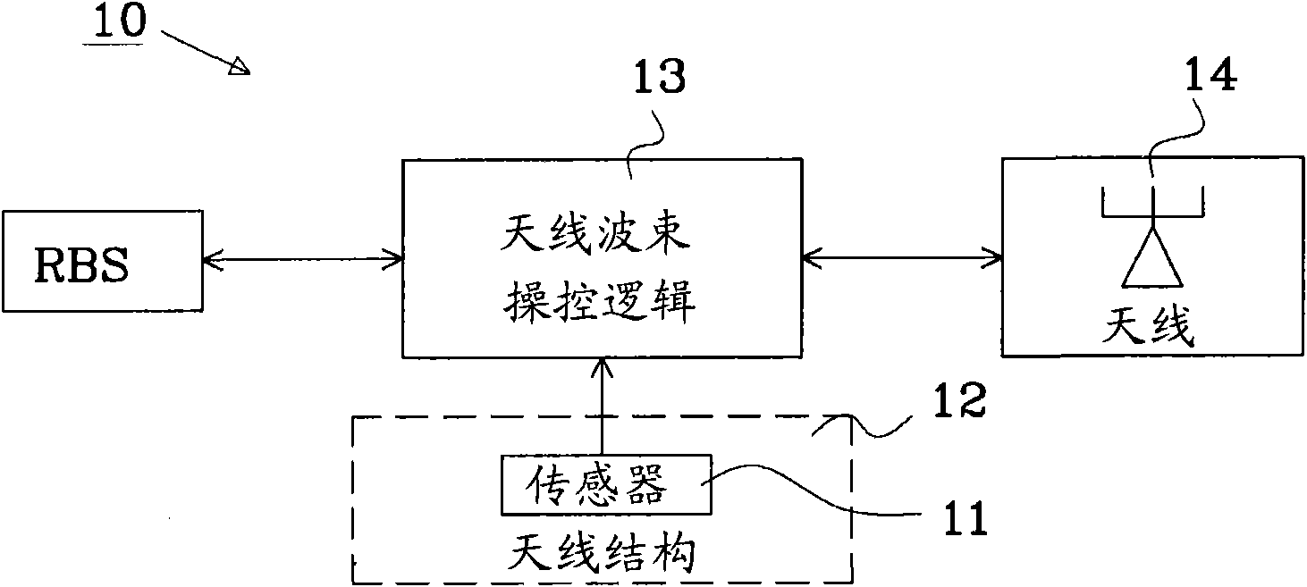
[0027] Figure 1 depicts a prior art beam steering arrangement 10 to counteract antenna tower sway. One or more sensors 11 are arranged on the antenna structure 12 . The detected sway of the antenna structure 12 is used to control the antenna beam steering logic 13 to dynamically adjust the beam by modifying the drive signal from the radio base station (RBS). The modified drive signal is provided to the antenna elements of antenna 14 .

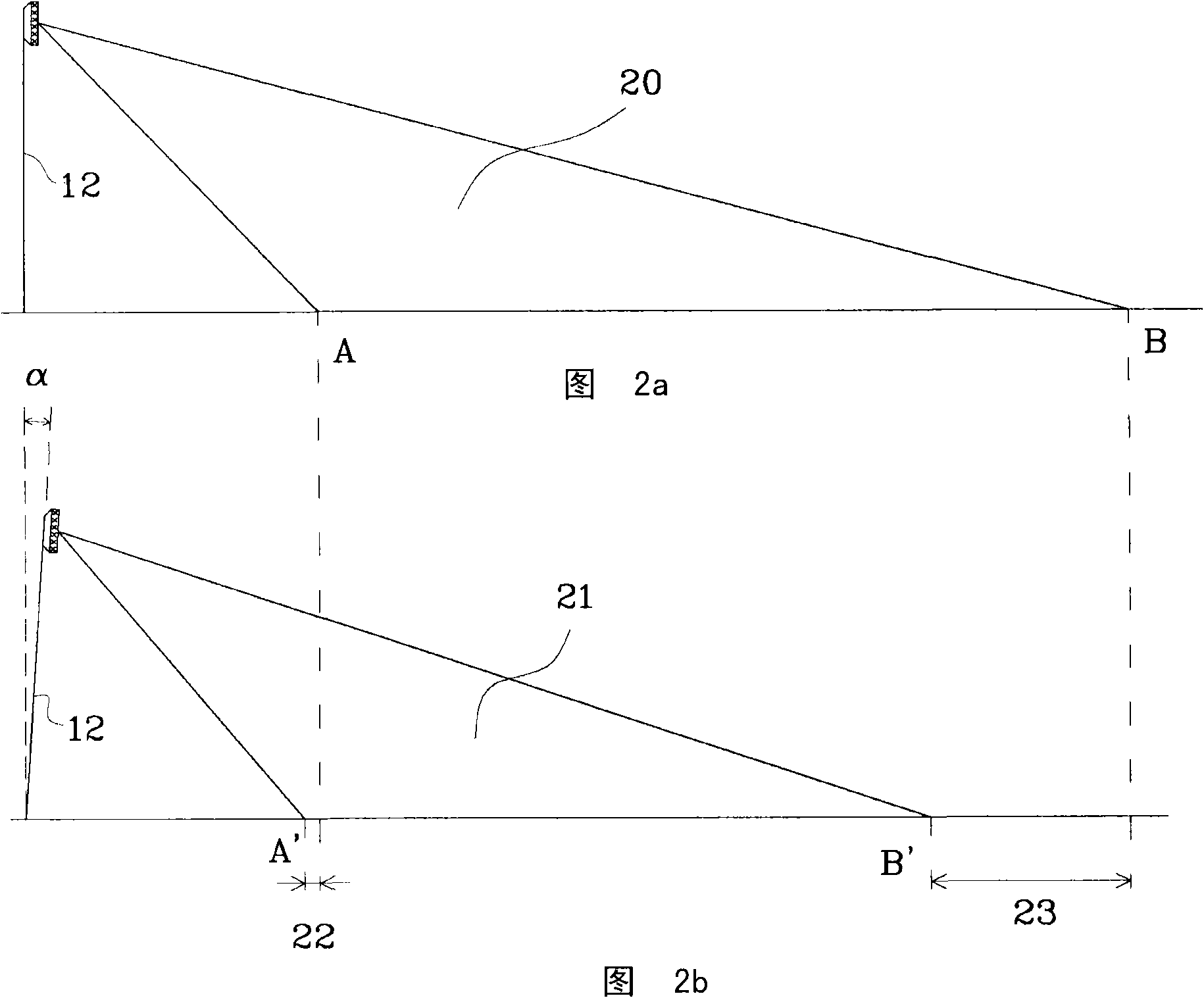
[0028] Figure 2a The antenna coverage of an unaffected (non-swaying) antenna structure 12 is illustrated, ie the antenna elements are arranged in a vertical reference plane. The antenna beam pattern 20 covers an area extending from point A to point B. As shown in FIG.

[0029] Figure 2b The antenna coverage of an affected (swaying) antenna structure 12 is illustrated, ie the antenna elements are tilted forward by an angle α. The tilted antenna beam pattern 21 covers a significantly smaller area than that of the unaffected antenna structur...


PUM


Abstract

The present invention relates to methods for adjusting a radiation beam pattern of an antenna arrangement providing coverage in an area. The antenna arrangement comprises an antenna having at least one array of antenna elements connected to a distribution network configured to generate the radiation beam pattern. The method comprises: arranging the antenna elements of said array in at least one column in an antenna plane in relation to a reference plane, each column comprising multiple antenna elements arranged in at least two sub-panels; arranging a motion sensor to the antenna arrangement, said motion sensor is configured to detect deviation of the antenna elements relative the reference plane; and adjusting a beam shape of the radiation beam pattern based on the detected deviation of the antenna to maintain coverage in the area by controlling the distribution network. The invention also relates to an antenna arrangement and base station.

Description

technical field [0001] The present invention relates to a method and a system for compensating the radiation beam of an antenna structure when the antenna structure is subjected to motion, ie movement or displacement. Background technique [0002] In many cases antennas are mounted to non-rigid or non-fixed structures, the motion of which can lead to time-varying antenna orientations when the structure is subjected to various forces. Thus, the direction of the radiation pattern of such antennas (eg, for directional antennas, this is measured relative to the main beam peak) will also vary with time. An example of such an installation situation is when the antenna is mounted on a pole or tower which moves (sways) when subjected to changing wind conditions (wind load). Such motion generally results in translation and rotation of the antenna. For typical base station antenna installations, the maximum antenna roll is on the order of ±1 degree (or less). [0003] The extent to...

Claims


Application Information

Patent Timeline
Patent Type & Authority Applications(China)
IPC IPC(8): H01Q1/00H01Q1/24H01Q3/30
CPCH01Q1/246H01Q1/005H01Q3/30
Inventor M·约翰逊S·O·彼得森
Owner OPTIS CELLULAR TECH LLC
Why Eureka
Try Eureka