
Self-locking protective sleeve and manufacturing method thereof

A self-locking, protective sleeve technology, applied to electrical components, insulators, etc., can solve the problems of easy disengagement, row size, poor locking stability of insulating line protection tubes, etc., and achieve strong structural adaptability and high stability Effect

Inactive Publication Date: 2010-04-07
长园科技集团股份有限公司
View PDF1 Cites 5 Cited by
  • Summary
  • Abstract
  • Description
  • Claims
  • Application Information

AI Technical Summary

Problems solved by technology

[0003] The technical problem to be solved by the present invention is to overcome the problems of poor locking stability, easy disengagement, and inability to adjust according to the diameter of the bare wire or the size of the bus bar in the existing insulating line protection tube, and propose a high locking stability , not easy to disengage, can be adjusted according to the diameter of the bare wire or the size of the busbar, good adaptability, a self-locking protective cover with a wide range of applicable bare wires and its preparation method

Method used


Image

  • Self-locking protective sleeve and manufacturing method thereof
  • Self-locking protective sleeve and manufacturing method thereof
  • Self-locking protective sleeve and manufacturing method thereof

Examples


Embodiment Construction

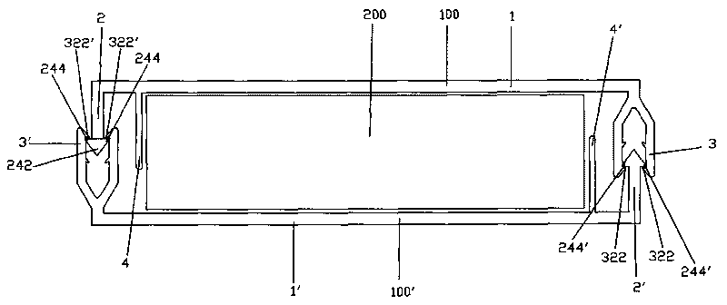
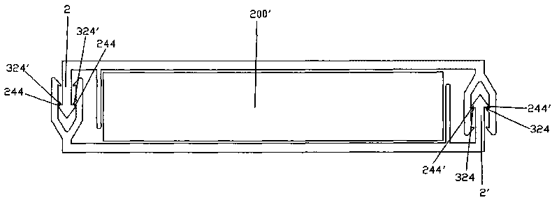
[0016] Such as figure 1 As shown, the present invention proposes a self-locking protective cover 100, which is made of plastic material and includes an insulating body 1, a snap-in piece 2 provided at one end of the insulating body 1, and a snap-in piece 2 provided at the insulating body 1. The snap-in piece 3 at the other end, and a blocking piece 4 arranged near the snap-in piece 2 .

[0017] The snap-in piece 2 includes a snap-in piece body 22 extending vertically upward from the insulating body 1 , and a triangular lock head 24 extending from the end of the snap-in piece body 22 .

[0018] The locking head 24 includes a triangular guide head 242 extending along the engaging piece body 22 and two triangular locking blocks 244 extending from the front end of the engaging piece body 22 to opposite sides.

[0019] The engaging member 3 includes two engaging pieces 32 extending upward from the insulating housing 1 . The two clamping pieces 32 are parallel, and there is a spac...


PUM


Abstract

The invention discloses a self-locking protective sleeve, which comprises an insulating body, a clamped piece arranged at one end of the insulating body and a clamping member arranged at the other end of the insulating body; the clamped piece comprises a clamped piece body extending upwards from the insulating body and a lock head formed by the extension from the end of the clamped piece body, wherein the lock head comprises a guide head formed by the extension from the clamped piece body and two clamping blocks formed by the extension respectively from the front end of the clamped piece body to two opposite sides; the clamping member comprises two parallel clamping pieces formed by the upward extension from the insulating body, a space for the clamping of the clamped piece is formed between two clamping pieces, the inner walls of two clamping pieces, in a downward, inward direction, are respectively extensively provided with at least two clamped legs corresponding to the clamping blocks, and these clamped legs can be clamped on the two clamping blocks to prevent the clamped piece from being withdrawn from the clamping member. Such a protective sleeve not only has high stability, but can also effectively prevent the clamped piece from being withdrawn from the clamping member, in addition, the adaptability is so strong that the same product can adapt to bare wires or busbars with various sizes.

Description

technical field [0001] The invention relates to an insulation protection device for a power transmission cable and a bus bar and a preparation method thereof, in particular to an insulation protection device for a power transmission bare wire and a bus bar and a preparation method thereof. Background technique [0002] At present, in our country, the power transmission cables in cities are generally buried underground, but the power transmission cables between cities and rural areas are generally overhead above the ground, and use bare wires to transmit electric energy. When the bare wires pass through the woods, they will cause a safety hazard. To this end, the utility model patent ZL 200520029479.8 "Snap-on insulating line protection tube" provides a solution, but the locking form of this patent is unilateral locking, and the stability of unilateral locking is poor, and it is easy to disengage. In the future, the purpose of insulation protection cannot be achieved. In add...

Claims


Application Information

Patent Timeline
Patent Type & Authority Applications(China)
IPC IPC(8): H02G3/04H01B17/58
Inventor 叶桂平王华新李江源
Owner 长园科技集团股份有限公司
Learn More