Supercharge Your Innovation With Domain-Expert AI Agents!

Ticket check machine based on RFID three-dimensional special-shaped antenna

A ticket gate and antenna technology, which is applied to ticketing equipment, induction record carriers, computer parts, etc., can solve the problems of increasing the recognition distance, short recognition distance, and insignificant effect, and achieves improved passing ability, low equipment cost, and ticket checking. Through powerful effects

Inactive Publication Date: 2010-04-14
大连现代高技术集团有限公司
View PDF0 Cites 2 Cited by
  • Summary
  • Abstract
  • Description
  • Claims
  • Application Information

AI Technical Summary

Problems solved by technology

[0002] At present, the radio frequency identification systems involved in the ticket gates in rail transit are all high-frequency RFID systems in the near-field working mode, which use the inductive coupling mode for communication, resulting in a short recognition distance. For ticket gates that require a large recognition distance Said, it is more difficult to increase the recognition distance
[0003] Secondly, the ticket gate has higher and higher performance requirements for single ticket processing time and passing capacity (person / min). Many manufacturers achieve this goal by improving software or redesigning the control system. The cost is greatly increased, but the effect is not significant.
In the processing time of a single ticket, the pre-reading and writing process of the ticket by the RFID reader takes up most of the time. According to the international standard requirements of contactless IC tickets, these times are difficult to reduce
[0004] Finally, for a ticket gate with a small space and part of the shell and frame must be metal, how to reduce the electromagnetic interference of the surrounding metal environment on the reader antenna, increase the correct reading rate of the ticket card, and improve the passing capacity is also a difficult problem. The problem

Method used


Image

  • Ticket check machine based on RFID three-dimensional special-shaped antenna
  • Ticket check machine based on RFID three-dimensional special-shaped antenna
  • Ticket check machine based on RFID three-dimensional special-shaped antenna

Examples


Embodiment Construction

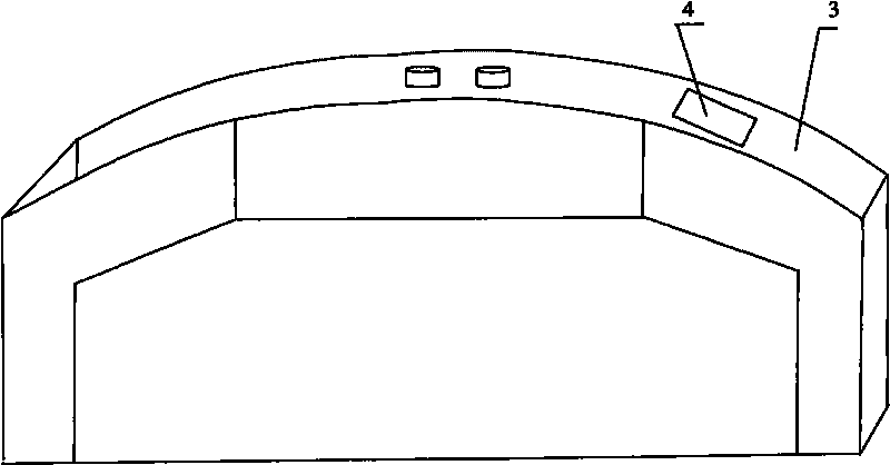
[0012] Such as figure 1 The casing structure of the ticket checking machine shown includes an arcuate shoulder surface 3 inclined forward and downward at the front and a ticket card entrance 4 provided on the upper end of the shoulder surface 3 .

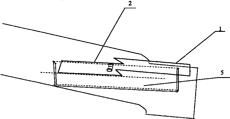
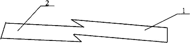
[0013] Such as figure 1 and 2 As shown, there is a card reader inside the casing of the ticket gate. The card reader is provided with a pair of RFID three-dimensional special-shaped antennas, which are composed of a pre-read antenna 1 and a card write antenna 2, both made of printed circuit boards, and they share a pair of feeders. The pre-reading antenna 1 is roughly parallel to the shoulder-to-shoulder surface 3 of the ticket gate machine casing; the card writing antenna 2 is parallel to the horizontal plane. Since the plane of the pre-reading antenna 1 is inclined, it forms an angle with the plane of the card writing antenna 2, and the two parts of the antenna are connected end to end. The connection method is as follows: fi...


PUM


Abstract

The invention discloses a ticket check machine based on a RFID three-dimensional special-shaped antenna. The ticket check machine comprises a machine shell and a card reader arranged inside the machine shell, wherein the machine shell comprises an arc-shaped shoulder surface (3) with the front part tilting forwards, and a ticket inlet (4) arranged at the upper end; the card reader includes a pre-read antenna (1) and a card writing antenna (2) which are made of a printed circuit board and share a pair of feeder lines, wherein the card writing antenna (2) is horizontally arranged at the rear lower part, and the pre-read antenna (1) is positioned under the shoulder surface (3) and consistent with the trend of the shoulder surface (3); and the rear end of the pre-read antenna (1) is connected with the front end of the card writing antenna (2) arranged at the rear lower part. On the premise of not changing the appearance, functions and cost of the existing ticket check machine in the prior art, the RFID three-dimensional special-shaped antenna is used for increasing the identifying distance of tickets, so that the ticket check machine shortens the ticket treatment time, improves the passing rate of reading and writing the tickets, and enhances the through capacity.

Description

technical field [0001] The invention relates to an automatic ticket sales and inspection system applied in rail transit, and more specifically, relates to the improvement of the antenna of the ticket inspection ticket card reader and writer in the ticket inspection system. Background technique [0002] At present, the radio frequency identification systems involved in the ticket gates in rail transit are all high-frequency RFID systems in the near-field working mode, which use the inductive coupling mode for communication, resulting in a short recognition distance. For ticket gates that require a large recognition distance In other words, it is more difficult to increase the recognition distance. [0003] Secondly, the ticket gate has higher and higher performance requirements for single ticket processing time and passing capacity (person / min). Many manufacturers achieve this goal by improving software or redesigning the control system. The cost is greatly increased, but the...

Claims


Application Information

Patent Timeline
IPC IPC(8): G07B11/00G06K7/00
Inventor 张士辰于洪增雷英哲施宁于延波于明武冯海波李丽武丹丹茹树华秦嘉川
Owner 大连现代高技术集团有限公司
Features
  • R&D
  • Intellectual Property
  • Life Sciences
  • Materials
  • Tech Scout
  • Unparalleled Data Quality
  • Higher Quality Content
  • 60% Fewer Hallucinations
Learn More