Coil winder

A wire winder and thread head technology, which is applied in coil manufacturing, cathode heater manufacturing, etc., can solve the problems of inconvenient operation, low efficiency, and large size, and achieve the effects of convenient operation, neat wiring, and improved work efficiency

Inactive Publication Date: 2010-04-14
常熟卓辉光电科技股份有限公司
View PDF0 Cites 5 Cited by
  • Summary
  • Abstract
  • Description
  • Claims
  • Application Information

AI Technical Summary

Problems solved by technology

[0002] In recent years, a large number of energy-saving lamps and other products have been developed and produced. During the production process, the energy-saving filament is wound on the terminal. However, in the actual production process, due to the large volume of the winding tool, it is inconvenient to operate and use. It requires manual work, and without special tools, it is impossible to ensure that the winding is neat, which affects product quality and is inefficient; for example, when the lead of the coil is wound on the lead pin (or lead post) of the transformer or inductor, the same problem also exists

Method used


Image

  • Coil winder
  • Coil winder
  • Coil winder

Examples


Embodiment Construction

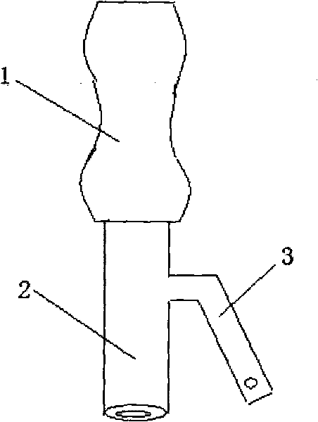
[0013] Such as figure 1 As shown, the wire winder includes: a handle 1 and a rotating handle 2, the rotating handle 2 is tubular, one end of which is arranged on the handle 1; Insert the turning handle 2 of the wire winder on the coil post where the wire needs to be wound, the thread end is fixed on the lead handle 3, and the handle 1 is rotated to drive the rotation of the turn handle 2 and the lead handle 3, so that the wire is wound on the coil post.

[0014] The handle 1 and the rotating handle 2 of the wire winder can be integrated, and only the rotating handle 2 can realize the function of the present invention. The function of the handle 1 is to realize the effective rotation of the wire winder.

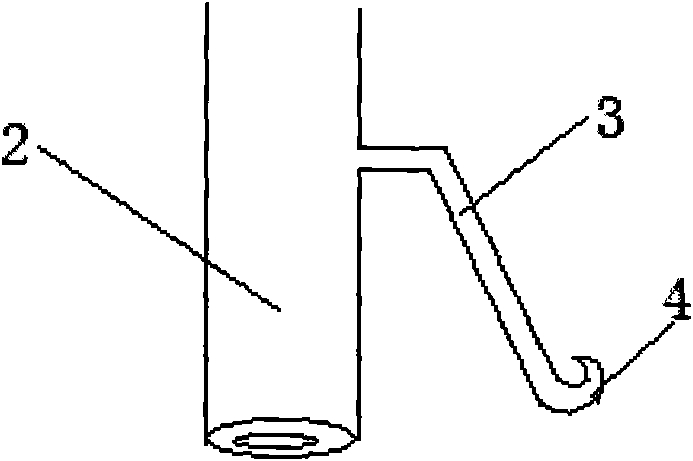
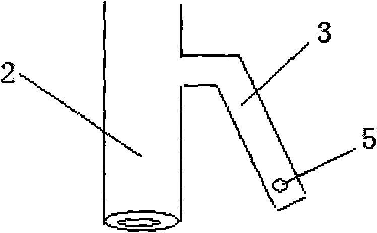
[0015] The effect of lead wire handle 3 is to fix thread end, is convenient to the rotation of wire winder, and its structure can be multiple, as long as thread end can be fixed on the lead wire handle 3 and get final product. figure 2 What is shown is a structure of the lea...


PUM


Abstract

The invention discloses a coil winder which comprises a handle and a tubular rotating handle, wherein one end of the tubular rotating handle is arranged on the handle, a lead handle for fixing the end of a coil is also arranged on the rotating handle; the rotating handle of the coil winder is inserted on a coil column to be wound by the coil, the end of the coil is fixed on the lead handle, at last, the handle is rotated to drive the rotation of the rotating handle and the lead handle so as to enable the coil to be wound on the coil column. The coil wound by the coil winder is neat, safe and reliable; meanwhile, by using the coil winder, the operation is convenient, and the working efficiency can be improved.

Description

technical field [0001] The invention relates to a wire winder used in electric power and electronic industry. Background technique [0002] In recent years, a large number of products such as energy-saving lamps have been developed and produced. During the production process, energy-saving filaments are wound on the terminal posts. It requires manual work, and without special tools, it is impossible to ensure that the winding is neat, which affects product quality and is inefficient; for example, when the lead of the coil is wound on the lead pin (or lead post) of the transformer or inductor, the same problem also exists . Technicians in this industry have been looking for a simple and practical winding tool. Contents of the invention [0003] The technical problem to be solved by the present invention is to provide a wire winder with a simple and practical structure, which can facilitate wire winding. [0004] In order to solve the above technical problems, the technic...

Claims


Application Information

Patent Timeline
Patent Type & Authority Applications(China)
IPC IPC(8): H01F41/06H01J9/10
Inventor 杨耀武苏怡
Owner 常熟卓辉光电科技股份有限公司
Why Eureka
Try Eureka